In any switching power supply design, the physical design of the PCB board is the last link. If the design method is improper, the PCB may radiate excessive electromagnetic interference and cause the power supply to work unstable. As a designer, you must understand the physical working principle of the circuit and design a high-quality PCB.

The switching power supply contains high-frequency signals. Any printed line on the PCB can function as an antenna. The length and width of the printed line will affect its impedance and inductance, thereby affecting the frequency response. Even printed lines that pass DC signals can couple to radio frequency signals from adjacent printed lines and cause circuit problems (and even radiate interfering signals again). Therefore, all printed lines that pass AC current should be designed to be as short and wide as possible, which means that all components connected to the printed lines and other power lines must be placed very close. The length of the printed line is proportional to its inductance and impedance, and the width is inversely proportional to the inductance and impedance of the printed line. The length reflects the wavelength of the printed line's response. The longer the length, the lower the frequency at which the printed line can send and receive electromagnetic waves, and it can radiate more radio frequency energy.
Choosing the right MOSFET for the design of power switch or synchronous rectification function can also help reduce electromagnetic interference. When the MOSFET device is powered off, low C▼oss▼ (like FDS6690A) can reduce spike interference.
Main current loop
The current loops of the three main switching power supply structures, pay attention to their differences.
Each switching power supply has four current loops, and the loops are relatively independent. On a well-layout PCB, the order of importance is as follows:
Power switch AC circuit
output rectifier AC circuit
Input signal source current loop
output load current loop
The input signal source and output load current loop usually have no problems. The current waveform in these loops is a superposition of a large DC current and a small AC current. These two loops usually require special filters to prevent AC noise from leaking into the surrounding environment. The input and output current loops should only be connected to the power supply from the terminal of the filter capacitor respectively. The input circuit charges the input capacitor through an approximate DC current, but it cannot provide the high-frequency current pulses required by the switching power supply. The filter capacitor mainly functions as a broadband energy storage; similarly, the output filter capacitor is also used to store the high-frequency energy from the output rectifier and at the same time eliminate the DC energy of the output load loop. Therefore, the terminals of the input and output filter capacitors are very important. If the connection between the input/output circuit and the power switch/rectifier circuit cannot be directly connected to the terminals of the capacitor, the AC energy will "flow through" the input or output filter capacitor And radiate to the environment.
The current waveforms of the two basic PWM operating modes produce harmonic current waveforms that are much higher than the switching frequency.
The AC circuit of the power switch and the rectifier contains a high-amplitude trapezoidal current waveform. The harmonic components in these waveforms are very high, and their frequency is much greater than the fundamental frequency of the switch. The peak amplitude of these AC currents can be as high as 5 times the amplitude of the continuous input/output DC current. The transition time is usually about 50ns. These two loops are the easiest to produce Electromagnetic interference.
The designer must lay out these AC loops before wiring other printed lines in the power supply. The three main components of each loop (filter capacitor, power switch or rectifier, inductor or transformer) should be placed adjacent to each other and adjusted Positioning the components so that the current path between them is as short as possible to ensure that the length of the current path is shortened.
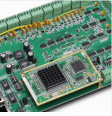
The printed lines in these circuits also have the greatest impact on the converter's measurement efficiency. Choosing packages such as DPAK or SO-8 can carry out signal transmission while dissipating heat. Products from Fairchild and other suppliers can combine the functions of heat dissipation and signal transmission.
Grounding is important
Grounding is the bottom branch of the current loop discussed earlier, but it plays an important role as a common reference point for the circuit. Therefore, the placement of the grounding wire should be carefully considered in the layout. Mixing various groundings will cause unstable power supply operation.
Three main grounding schemes of switching power supply structure.
The design should make sure that another "control ground" has been considered. It is the grounding point connected to the control IC and all related passive components and is extremely sensitive. Therefore, it should be placed only after other AC circuits are laid out. The point where the control ground is connected to other grounds is very special. Usually, the connection point is located at the common end of all the components of the control IC that induce a small voltage. These connection points include the common end of the current-sensitive resistor in the current-mode switching converter and the bottom end of the output resistor divider. Its function is to establish a low-noise Kelvin between the sensitive element and the input that is sensitive to voltage errors or current amplification. connect. If the control ground is connected to any other point, the noise generated in those extra loops will be superimposed on the control signal, which will affect the operation of the control integrated circuit.
The designer must ensure that each high-current ground terminal uses a printed line as short and wide as possible. Generally, the common terminal of the filter capacitor should be the only connection point for coupling other grounding points to the high-current AC ground.
High voltage AC node
There is a node in each switching power supply. Compared with other nodes, its AC voltage is the highest. This node is the AC node that appears at the drain (or collector) of the power switch. In a non-isolated DC/DC converter, this node can also be connected to the inductor and (or output to) the rectifier; in the structure of the isolation transformer, this node is separated from the coil of the transformer. It still appears as a public node in electrical performance, but it is only reflected by the transformer, and each one needs to be designed separately.
This node will have different problems. Its AC voltage can be capacitively coupled to the printed lines of different metal layers nearby and radiate electromagnetic interference. However, printed lines usually must also dissipate heat for power switches and rectifiers, especially for surface-mounted power supplies. From an electrical point of view, the printed line should be as small as possible, but from a heat dissipation point of view, it should be larger. In the design of surface mounting, there is a good compromise method, making the top PCB board the same as the bottom PCB board, and connecting them together through many holes (or vias).
A good way to enhance the heat dissipation capacity of the PCB board and reduce the capacitive coupling of other printed lines.
This technology greatly reduces the capacitive coupling to other printed lines, but it doubles the heat dissipation and surface area. Take a SO8 packaged N-channel power MOSFET (such as FDS6670A) as an example. There is only a 325 mm ▲ 2 ▲ copper area on the upper layer, and the thermal resistance in contact with air is 50 (C/W, plus another on the bottom layer of the PCB). A same board connected together through 8 vias, the thermal resistance is reduced to 39 (C/W, because there are no metal wires carrying different signals on the other side of the board, the capacitance of the capacitor will drop by more than an order of magnitude.
In via hole applications, other signals and grounding must be kept away from high-voltage AC printed lines and parts used for heat dissipation. In an offline converter, the ground wire may couple energy from this node and lead it out of the product through the AC plug, which generates excessive conducted electromagnetic interference.
Parallel filter capacitor
Capacitors are often used in parallel to reduce the parallel equivalent series resistance (ESR) of the filter capacitor. This approach also allows each capacitor to shunt part of the ripple current so that each capacitor can work normally within its ripple current specification. Only when the printed line impedance between the capacitors and each ripple current source are the same, the ripple current will be "averaged", which requires that the printed lines between the capacitors between the rectifier or the power switch tube must be of equal length and width .
The correct placement of parallel capacitors is one of the keys to the design of switching power supplies.
It is very beautiful to place capacitors in columns and connect them in sequence. However, this layout will make the capacitor closest to the power switch or rectifier bear more ripple current than other capacitors, thus shortening the service life of the capacitor.
The above is an introduction to the PCB design of embedded switching power supplies. Ipcb is also provided to PCB manufacturers and PCB manufacturing technology.