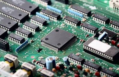
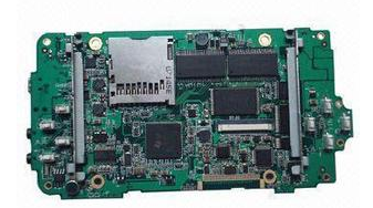
1. Reasons for short circuit during PCBA production and processing
This problem is one of the common faults that will directly cause the PCB board to not work. There are many reasons for this problem. Let's analyze one by one.
1) The biggest cause of PCB short circuit is improper solder pad design. At this time, the round solder pad can be changed to an oval shape to increase the distance between points to prevent short circuits.
2) Inappropriate design of the direction of the PCB parts will also cause the board to short-circuit and fail to work. For example, if the pin of the SOIC is parallel to the tin wave, it is easy to cause a short-circuit accident. At this time, the direction of the part can be appropriately modified to make it perpendicular to the tin wave.
3) There is another possibility that will cause short-circuit failure of the PCB, that is, the automatic plug-in bent foot. As the IPC stipulates that the length of the pin is less than 2mm and there is concern that the parts will fall when the angle of the bent leg is too large, it is easy to cause a short circuit, and the solder joint must be more than 2mm away from the circuit.

In addition to the three reasons mentioned above, there are also some reasons that can cause short-circuit failure of the PCB board, such as too large a hole in the substrate, too low temperature in the tin furnace, poor solderability of the board, failure of the solder mask, and board Surface pollution, etc., are relatively common causes of failures. Engineers can compare the above causes with the failure conditions to eliminate and inspect them one by one.
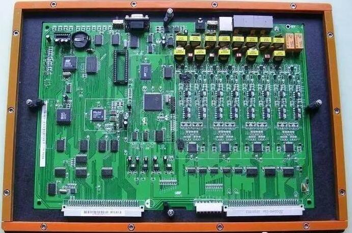
Two, PCBA test
PCBA testing mainly includes five forms: ICT test, FCT test, aging test, fatigue test, and test under harsh environment.
1. ICT test: including circuit continuity, voltage and current values and fluctuation curves, amplitude, noise, etc.
2. FCT test: IC program firing is required to simulate the function of the entire PCBA board, find the problems in the hardware and software, and be equipped with necessary production fixtures and test racks.
3. Fatigue test: sample the PCBA board and perform high-frequency and long-term operation of the function to observe whether there is failure and judge the probability of failure in the test, so as to feedback the working performance of the PCBA board in the electronic product.
4. Test in harsh environments: Expose the PCBA board to extreme temperature, humidity, drop, splashing, and vibration to obtain random sample test results, thereby inferring the reliability of the entire PCBA board batch product.
5. Aging test: The PCBA board and electronic products are energized for a long time, keep them working and observe whether there are any failures. After the aging test, the electronic products can be shipped in batches.
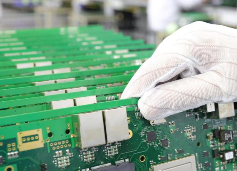
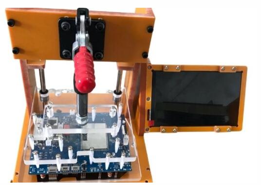
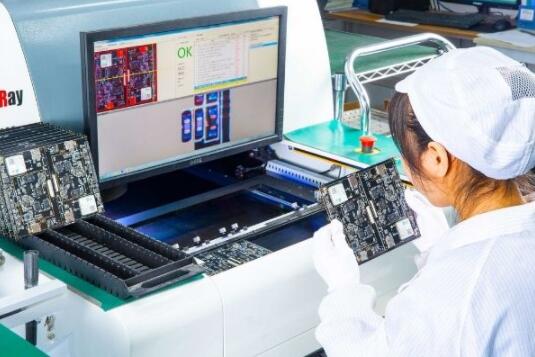
Inspection Machine-First Article Inspection Instrument
The SMT intelligent first-piece inspection instrument intelligently integrates the CAD coordinates, BOM list and the first PCB scan. The system automatically enters the measurement data, does not allow manual data entry, eliminates human error and omission, and realizes the first-piece inspection of the SMT production line to simplify the first-piece inspection. The inspection efficiency has been greatly improved, achieving high efficiency and high quality.
1) Import files, BOM list and stencil printing to the machine in advance, and use tools to check all parts.
2) Check the capacitance and resistance. For other parts, we will carefully check the direction of the stencil printing.
3) The inspection report can be derived from the computer. The purpose of this step is to control the quality, so that problems can be found in the early stage and the loss can be stopped in time.
4) After completing this step, the first board or panel will pass the reflow soldering within 5-7 minutes. Then the engineer took out the first board for programming and functional testing. When everything is fine, we will start mass production.