This article is mainly about the specific process and common tools of smt patch processing factory smt patch processing
The following is an introduction to the specific process and common tools of smt patch processing factory smt patch processing:
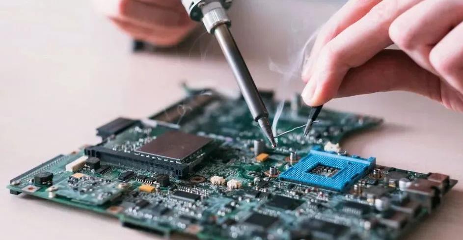
Tweezers: Use stainless steel and sharp tweezers instead of other magnetic tweezers, because the magnetic tweezers will make the components stick to the upper and lower tweezers during the welding process.
Electric soldering iron: Choose an electric soldering iron with a conical long-life soldering iron tip, with a radius of less than 1mm, and prepare two soldering irons, which are convenient to use when disassembling components.
Hot air gun: When disassembling two-terminal or three-terminal components, an electric soldering iron can be used. However, a hot air gun must be used when disassembling multi-lead components. The heat gun can improve the reusability of the disassembled components and avoid damage to the PCB pads. For frequent work of disassembling components, a hot air gun with good performance is required.
Suction tape: When the IC lead wire is short-circuited, it is a very good choice to use a suction tape. At this time, a solder suction device cannot be used.

Magnifying glass: Use a magnifying glass with a lamp tube with a base instead of a hand-held magnifying glass. Because it is necessary to use both hands under a magnifying glass when welding, the lamp can be lit to make the field of vision clear and increase the visibility of welding.
1. Component patch data
Simply put, the component placement data is to specify the position, angle, model, etc. of the components to be placed on the PCB. The patch data includes component model, tag number, X coordinate, Y coordinate, placement angle, etc. The origin of the coordinate is generally taken at the lower left corner of the PCB.
2. Benchmark data
Including reference point, coordinates, color, brightness, search area, etc. Before the placement cycle starts, the night vision camera on the placement head will first search for benchmarks. After the reference is found, the camera reads its coordinate position and sends it to the placement system microprocessor for analysis. If there is an error, the computer issues instructions and the placement system controls the execution of the component to move, thereby positioning the PCB. There should be at least two reference points to ensure the positioning of the PCB
3. Component database
There are component sizes, pin numbers, pin spacing, and corresponding nozzle types in the library.
4. Feeder arrangement data
The feeder arrangement data specifies the feeder selected for each component and the placement position on the placement machine's feeding platform.
5. PCB data
PCB data includes setting the size, thickness, and board data of the PCB.
The above is an introduction to the specific process and common tools of smt patch processing factory smt patch processing plant, smt patch processing plant staff should master its skills, improve their own work skills, so as to improve production rate and product quality.