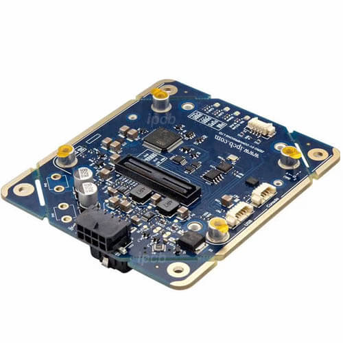
Millimeter wave radar PCBA
PCB layers: 4 - 6 layers
Substrate: RO3003 + Isola 370HR
PCB Surface treatment: Immersion silver
PCB Copper thickness: 1oz
PCB Color: Green, Black, White, Red, Blue
PCB Testing: Yes
Chip: Texas Instruments IWR1843BOOST
PCBA Testing: No
Application: Millimeter wave radar
76GHz to 81GHz FMCW Millimeter Wave Sensor
Millimeter wave radar is one of the main sensing methods for automotive and industrial applications because it can detect objects from a few centimeters to several hundred meters with high-precision distance, angle and speed accuracy even under harsh environmental conditions.
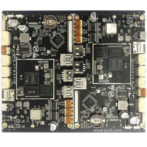
Typical millimeter wave radar PCBA includes a radar chipset and other electronic components, such as a power management circuit, flash memory and peripheral interface devices assembled on PCB. The transmitting and receiving antennas are also usually realized on PCB, but to achieve high antenna performance, high-frequency PCB materials, such as Rogers RO3003 and Isola 370hr, need to be used.

The core components of millimeter wave radar include a transceiver antenna (TX&RX), radio frequency unit (RF), analog to digital converter (ADC), digital signal processor (DSP), microcontroller (MCU), etc. RF, ADC, DSP, MCU, etc. are directly integrated into one SOC through the CMOS process.
Millimeter wave radar mainly uses four frequency bands of 24GHz, 60GHz, 77GHz and 79GHz. 24GHz belongs to centimeter wave accurately. Due to the limited measurement distance (about 60m) and general resolution, it is often designed as an angle radar to detect close range obstacles in a wide field of view angle range. Because 60GHz is particularly affected by atmospheric attenuation, it is often designed as a vital sign detection radar to detect the vital signs and personnel posture in the vehicle. 77GHz and 79GHz are often designed as primary radars because of their long measurement distance (about 200m), which are powerful tools for forward long distance perception. These two bands are also the mainstream bands in the future vehicle mounted millimeter wave radar field.
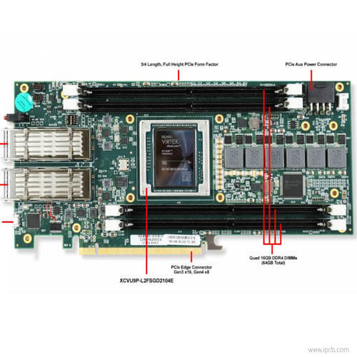
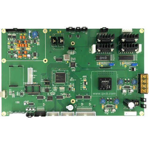
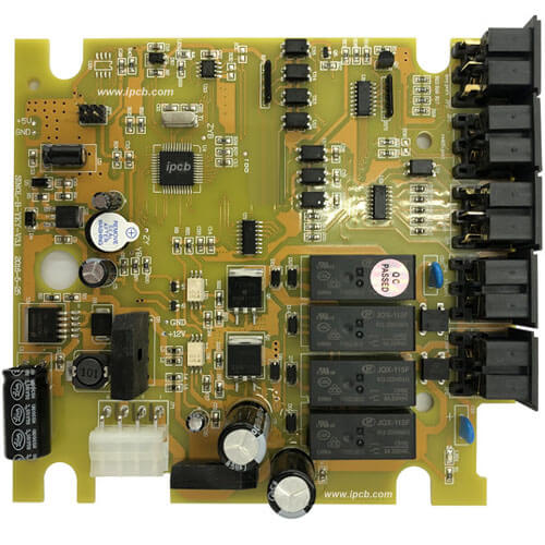
Inductors, capacitors, diodes, power chips, etc. are densely erected on the power supply motherboard, which is mainly responsible for system power management. Each company will generally integrate a safety controller on it to provide vehicle communication and safety related functions.
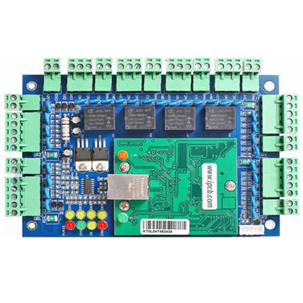
The radar motherboard can be said to be the core of the whole millimeter wave radar, including the antenna, RF, DSP and control circuit board.

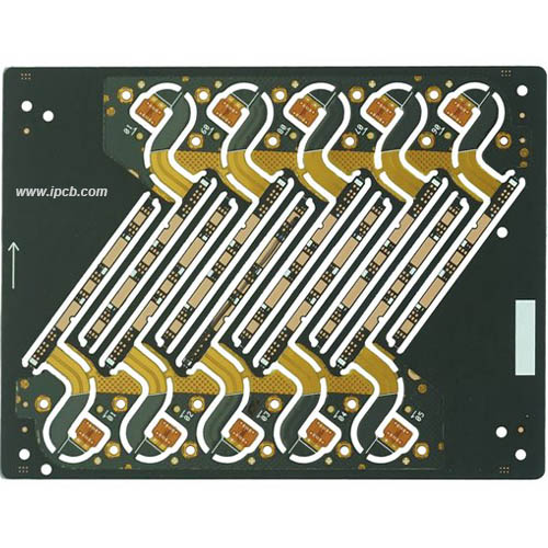
Millimeter wave radar antenna PCBA
When the length of the antenna is 1/4 of the electromagnetic wave length, the transmission and reception conversion efficiency of the antenna is the highest. The wavelength of millimeter wave is only a few millimeters, so the antenna can be made very small. By using multiple antennas to form an array antenna, narrow beam can also be achieved, and narrow beam means higher azimuth resolution.
At present, the mainstream scheme of millimeter wave radar antenna is microstrip array. The most common design is to integrate the microstrip patch antenna on the high-frequency PCB and integrate the high-frequency PCB on the radar motherboard. This scheme greatly reduces the cost and volume of millimeter wave radar.
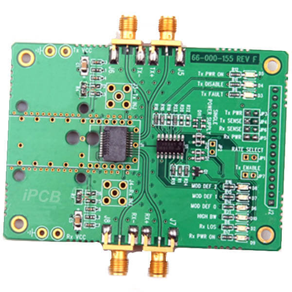
Millimeter wave radar RF PCBA
RF is responsible for signal modulation, transmission, reception and echo signal demodulation. It is the core RF part of millimeter wave radar. At present, the mainstream solution is to integrate the above contents through MMIC (Monolithic Microwave Integrated Circuit) technology. MMIC is a technology for manufacturing passive and active components on semiconductor substrate by semiconductor technology.
In the field of millimeter wave radar, MMIC integrated functional circuits based on silicon germanium technology mainly include low-noise amplifier, power amplifier, mixer, detector, modulator, voltage controlled oscillator, phase shifter, switch and other components. The transmitter, receiver and DSP are all independent units, which makes the design process of millimeter wave radar complex and the overall volume relatively large.
With the development of COMS technology, MMIC becomes smaller on the one hand, and on the other hand, it provides technological feasibility for its integration with DSP and MCU. At the end of 2016, TI launched a highly integrated 77GHz millimeter wave radar chip AWR1642 based on CMOS technology, integrating front-end MMIC, DSP and MCU on a single SOC. While significantly reducing the cost of millimeter wave radar, it also greatly reduces the difficulty of development.
DSP of millimeter wave radar PCBA
By embedding different signal processing algorithms, DSP extracts IF signals collected from the front end to obtain specific types of target information. DSP is the core of stability and reliability of millimeter wave radar.
Control Circuit of Millimeter Wave Radar PCBA
The control circuit of millimeter wave radar carries out data fusion according to the target information output by DSP and the vehicle body dynamic information, and finally carries out decision processing through the main processor.
According to the different ways of radiating electromagnetic waves, millimeter wave radars are mainly divided into two types: pulse wave operating system and continuous wave operating system.
Pulse wave technology refers to that millimeter wave radar transmits short pulses with peak power in a short time, realizes object speed and distance measurement based on Doppler frequency and TOF principle, and realizes angle measurement based on phase difference of pulse wave reflected by the same target received by parallel receiving antenna. Because of its high power, it can detect moving targets with small amplitude in a long distance in the background of large clutter. But it also brings the disadvantages of high cost, high volume and high power consumption. At present, this method is rarely adopted in the field of vehicle mounted millimeter wave radar.
Continuous wave technology can also be divided into FSK (frequency shift keying, which can measure the distance and speed of a single target), CW (constant frequency continuous wave, which can only be used for speed measurement but not for distance measurement) and FMCW (frequency modulated continuous wave). Among them, FMCW has become a common technology in continuous wave technology due to its advantages of simultaneous detection of multiple targets, high resolution and low cost.
After receiving the transmitted electromagnetic wave from the millimeter wave radar receiving antenna, the echo signal and the transmitted signal will be sent into the mixer for mixing. As the transmitted signal encounters the measured target and returns, the frequency of the echo signal has changed compared with the transmitted signal. The purpose of the mixer is to calculate the frequency difference between the transmitted signal and the echo signal, which is called IF signal. The IF signal contains the range secret of the measured target, and the range information of the measured target can be obtained after subsequent processing such as filtering, amplification, analog-to-digital conversion and frequency measurement.
For velocity measurement, the phase of echo signal received by millimeter wave radar will be different due to the different distance of the measured target. All single chirp signals in a frame are sampled at equal intervals, and the data at the sampling points are fourier transformed, then the velocity of the measured target is measured by using phase difference.
For angle measurement, multiple receiving antennas are used to receive the same echo signal and calculate the phase difference between echo signals to achieve angle measurement.

3D millimeter wave radar
Millimeter wave radar can only output distance, speed and angle information, which is also called 3D millimeter wave radar. And this distance D and angle θ It is the data of the self vehicle installed with radar in the plane polar coordinate system. By converting the polar coordinate system to the Cartesian coordinate system, we can obtain the distance from the target vehicle to the self vehicle in the x and y directions. At this time, do you find that the distance in the z direction of the dimension is missing. This is also one of the shortcomings of 3D millimeter wave radar that has been criticized.
However, this disadvantage is fatal to static objects. The manhole covers, speed bumps, various signs hanging in the midair, elevated structures, stationary vehicles, etc. in the middle of the road can not be determined by 3D millimeter wave radar whether these obstacles affect the traffic due to the lack of height information. For static objects, manufacturers are simple and crude, either directly ignoring or greatly reducing the confidence. This is also one of the reasons for Tesla's earlier accidents. The camera did not identify the fallen white freight car, and the millimeter wave radar did. However, the confidence in decision-making was too low, resulting in the vehicle not triggering the automatic emergency automatic function.
4D millimeter wave radar
The most remarkable feature of 4D millimeter wave radar is that it can accurately detect the pitch angle, so as to obtain the true height data of the measured target, that is, the distance of the target object in the z axis direction in the Cartesian coordinate system. With this feature, the 4D millimeter wave radar can identify stationary objects, and the shortest piece of wood has been added. In addition, the resolution of 4D millimeter wave radar has also been greatly improved. Its horizontal and vertical resolutions are 1 ° and 2 ° respectively, and its horizontal resolution is 5-10 times higher than that of ordinary 3D millimeter wave radar.
Millimeter wave radar PCBA
PCB layers: 4 - 6 layers
Substrate: RO3003 + Isola 370HR
PCB Surface treatment: Immersion silver
PCB Copper thickness: 1oz
PCB Color: Green, Black, White, Red, Blue
PCB Testing: Yes
Chip: Texas Instruments IWR1843BOOST
PCBA Testing: No
Application: Millimeter wave radar
76GHz to 81GHz FMCW Millimeter Wave Sensor
For PCB technical problems, iPCB knowledgeable support team is here to help you with every step. You can also request PCB quotation here. Please contact E-mail sales@ipcb.com
We will respond very quickly.