Design the first batch of circuit boards to always work at DC or low speed, and any signal integrity initial board of the connector is used for low-frequency measurement of electrochemical sensors. The only circuits involved are low-pass filter circuits with through-hole passive components, PCB-mountable connectors for laboratory-grade power supplies, and parallel connections with SMUs. After understanding the details of signal integrity, those early circuit boards seemed very simple.
Choosing a connector is both an art and a science. The artistic aspect is about aesthetics and satisfactory gaps, while the scientific aspect is about signal integrity. For PCB mountable connectors, you need to choose between surface mount connectors or through-hole connectors, and you need to consider how each type affects the signal integrity in the application. The following are the things that need to be considered beyond the standard connector specifications.
Through hole and SMD PCB mountable connectors
When looking for a connector that can be mounted on a PCB, there are already many things to consider. To learn more about the basic electrical specifications of the connector.
In addition to the points mentioned in the above article, there are some points related to signal integrity and assembly that need to be considered. Regarding assembly, when the mechanical strength of the connector is stronger than theSMD solder joint, the through-hole connector is the first choice. If the connector will be plugged and unplugged repeatedly (such as a power jack), a through-hole connector should be used because it has a longer service life.
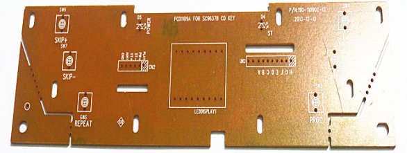
Through hole (left) and surface mount (right)

Regarding signal integrity, signal bandwidth will be the main determinant of factors such as insertion loss/return loss of the connector structure. This will set the -3 dB frequency in the insertion loss spectrum, effectively determining the usable bandwidth. Regarding signal integrity, there are two other important points to consider...
Pay attention to the rise time
Just like transmission lines on a PCB, the electrical length of the connectors determines when their impedance becomes important for termination. At low frequencies, the connector impedance is not important because its electrical length is very long, and we can ignore any impedance mismatch between the connector and its trace. The electrical length of the connector is determined in the same way as the critical length of the transmission line.
When working at high frequencies (for example, a few GHz or higher), impedance matching becomes important. For this reason, connectors for high-speed/high-frequency applications are designed to have a specific impedance (for example, an SMA connector with 50 ohm impedance) or a terminal block (for example, a BNC connector for arbitrary impedance matching).
Pay attention to the data rate
Do not equate data rate with bandwidth when searching for connectors. PCB mountable connectors for digital systems have a specific data rate. Be careful when converting data throughput to signal bandwidth, as the two are not equivalent. For binary signaling, an easy way to convert between bandwidth (B) and data rate (D) is to use the approximate value D = 2B. In fact, due to the use of multi-level signaling, the data rate can be much higher than twice the bandwidth.
How to deal with short wires in through-hole PCB mountable connectors?
If a through-hole PCB is used to mount the connector, the through-hole connection may protrude below the connection trace. In this case, the connector shaft is like a stub. This produces the same effect as the stub on any other transmission line, resulting in reflections due to impedance mismatch or resonance in the stub structure. I have seen discussions on some forums about the possibility of drilling back into connector stubs, but there are simpler (and cheaper) solutions than dealing with connector stubs.
Connector placement
The standard way to place the connector is to place the through-hole connector on the other side of the trace to which its connecting shaft will be soldered. The connection is provided by through holes. In this case, the connection is like a very short transmission line instead of a stub, so it will not affect impedance matching at low rise times. Once the WiFi frequency is exceeded, you need to worry about the impedance of the through-hole connection. At such high frequencies, only edge-mounted connectors are required.
SMD trace connection with through-hole ground rod
Some connectors have through-hole ground stakes to provide mechanical stability, but the center conductor is end-launched or surface mounted. This is a great way to eliminate stubs while providing mechanical stability. An example of a 26.5 GHz SMA connector is shown below.
26.5 GHz SMA connector with through-hole grounding stakes and end launch solder joints.
Use shorter through-hole connectors
Simply changing the design to accommodate through-hole connectors with smaller stubs is a good solution. For things like SMA connectors, unless you switch to edge-mounted or surface-mounted connectors, you won’t have many options. You may see some cost savings in the process, but you may have to sacrifice space. The various requirements of the connector need to be balanced, especially when considering the need for interfacing with external systems.
PCB factories should master PCB mounting connectors SMD and through holes