The hidden worries of lead-free soldering of circuit boards(4) Hot cracking of plates
First, the plate is cracked
(1) Explosion due to thermal cracking
It can be seen from the foregoing that not only the soldering temperature of SA C lead-free soldering rises by an average of 2 5-3 O degree Celsius, but the duration of the liquid state above the melting point (TA L) also stretches from 60 seconds to 90 seconds on average. This extra high heat (Therma1 Mass) will cause the sheet resin to deteriorate in terms of physical and chemical properties. In the large thermal expansion and contraction of the PCB, the XY direction has no problems due to the co-clamping of the glass fiber cloth, but the board thickness in the Z direction with less restriction will cause the board to burst. The thicker the board, the larger the area, the easier it is to burst. Usually a piece of PCB may be soldered more than three times (fusion soldering, wave soldering, heavy hand soldering). If the resin has poor heat resistance, lead-free soldering often causes partial delamination of the board.
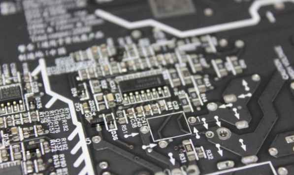
On the left is the solder joints of chip resistors, where many problems will occur during temperature cycling; on the right is the CSP ventral ball solder joints, which are broken due to the CTE drop.
(2) Measurement and description of resin T g
The heat resistance of current lead-welded plates is based on the T g of the cured resin as the criterion; plates with high T g have heat resistance, chemical resistance, solvent resistance, and mechanical strength, etc. Of course, it is better than the one with lower T g. However, in the lead-free era with higher calories, the heat resistance of various resins is no longer fully expressed by simple T g.
Circuit board manufacturers usually have three methods for measuring plate resin, namely: thermal mechanical analysis method TMA, differential scanning card meter method DSC, and dynamic mechanical analysis method DMA. Among them, TMA uses the principle of heating and thickening to obtain measurements and is more credible; DSC is an analysis method that uses changes in heat flow during heating, which is about 5°C higher than TMA. As for DMA, it will be higher than 15°C. Figure 8 is an explanation of TMA measuring resin Tg. In the figure, the first straight line after the extrapolation extends the virtual connection, and the second straight line that is imaginary connection with the extrapolation, the horizontal axis corresponding to the imaginary intersection point of the two straight lines, namely It is the T g temperature measured by TMA.
(Two), high temperature explosion-proof board T260 or D288
 Hot cracking of plates")
The so-called T260 refers to the time to delamination that the laminated board can resist bursting in a high temperature environment and maintain a complete duration (Time to Delamination). The test method is based on the "Therma1 Mechanic. Analysis" (TM A) used to analyze Tg as an instrument. The sample is heated from the bottom to an ambient temperature of 260°C in a closed test vessel to test its resistance. The number of minutes that may be experienced by the delamination in the Z direction. The correct expression is TMA260, abbreviated as T260.
The multilayer board after pressing is taken as the sample, the thickness is not limited, generally 1.6 mm is the main one, but the thicker the board, the easier it is to burst. Some backplane manufacturers often compare the selection of materials with thick plate samples of more than 5 mm to distinguish the heat resistance of different brands of resin in the Z direction.
The sample must be baked at 105°C for 2 hours to remove water. Then place the sample on the sealed heating test dish attached to TMA, apply 5 g pressure on the top of the sample with a sensitive barbed glass rod, and heat the test dish at a temperature increase rate of 10°C/min from room temperature until 260 The temperature will not increase until degree Celsius. Then start timing at a constant temperature of 260°C and carefully observe the changes in plate thickness. When the thermal expansion reaches a relatively stable thickness, pay attention to its fluctuations. Until the thickness data soared sharply, and no intermittent ups and downs, and reached the irreversible situation, the end of the test has been reached. The time to resist bursting in this 260°C environment is called T260.
Common Tgl 4 0 with a thickness of 1.6 mm in FR 4, its 7260 is between 4 and 5 minutes. For the current lead solder, it only takes more than two minutes. These plates are safe at high temperatures. NS. If the resin is another polyimide (P I), the test temperature must be increased to 288 degree Celsius and upgraded to T288 test. At present, many users of backplanes or large boards have switched to T288 to cope with the more difficult heat-resistant environment. In the new version of IPC-4 1 0 1 B (2 0 0 5.2), the T2 60 must be 30 minutes or more for the lead-free soldering plate test, and T288 also requires at least 15 minutes to be a minimum pass. Standard Huai, the only way to be more secure.