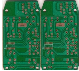
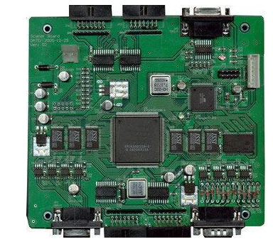
When a printed circuit board (PCB) manufacturer receives a quotation for a multi-layer design and the material requirements are incomplete or not stated at all, the choice of PCB core thickness becomes a problem. Sometimes this happens because the combination of PCB core materials used is not important to performance; if the overall thickness requirements are met, the end user may not care about the thickness or type of each layer.
But at other times, performance is more important, and the thickness needs to be strictly controlled to make the board perform the best. If the PCB designer clearly communicates all the requirements in the document, then the manufacturer will understand the requirements and set the materials accordingly.
Questions that PCB designers need to consider
It helps designers understand the materials available and commonly used materials, so they can use appropriate design rules to quickly and correctly build the PCB. What follows is a brief description of the types of materials that manufacturers prefer to use, and which materials they may need for quick rotation work without delaying your project.
Understand PCB laminate cost and inventory
It is important to understand that PCB laminate materials are sold as "systems" and work in "systems", and the core material and prepreg that the manufacturer keeps for immediate use are usually from the same system. In other words, the constituent elements are all parts of a specific product, but with some variations, such as thickness, copper weight, and prepreg style. In addition to familiarity and repeatability, there are other reasons to stock a limited number of laminate types.

The prepreg and core system are formulated to work together, but they may not work correctly when combined with other products. For example, Isola 370HR core material will not be used in the same stack as Nelco 4000-13 prepreg. They may work together under certain circumstances, but it is more likely that they will not. Hybrid systems take you into uncharted territory where the behavior of materials (which is well known when used as a homogeneous system) is no longer taken for granted. Careless or unknowing mixing and matching of material types can cause serious failures, so unless it turns out that the type is suitable for "hybrid" stacking, no manufacturer will mix and match.
Another reason for maintaining a narrow material inventory is the high cost of UL certification, so the number of certifications is usually limited to a relatively small range of material options in the PCB industry. Manufacturers usually agree to manufacture products on laminates that do not have a standard inventory, but it should be noted that they cannot provide UL certification through QC documents. If it is disclosed and agreed in advance, and the manufacturer is familiar with the processing requirements of the laminated system in question, then this is a good choice for non-UL designs. For UL work, it is best to find the manufacturer's inventory of your choice and design a circuit board that matches it.
IPC-4101D and foil structure
Since these facts are public, there are two other things you need to know before jumping into the design. First, it is best to specify laminates according to the industry specification IPC-4101D, rather than naming specific products that not everyone can stock.
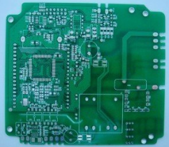
Second, it is easiest to construct multiple layers using the "foil" construction method. The foil structure means that the top and bottom layers (outside) are made of a piece of copper foil and laminated to the remaining layers with prepreg. Although it seems intuitive that you can build an 8-layer PCB with four double-sided cores, it is preferable to use the foil on the outside first, and then use the three cores for L2-L3, L4-L5, and L6-L7. In other words, plan to design a multi-layer stack so that the number of cores is as follows: (total number of layers minus 2) divided by 2. Next, it is useful to know some knowledge about core characteristics. they themselves.
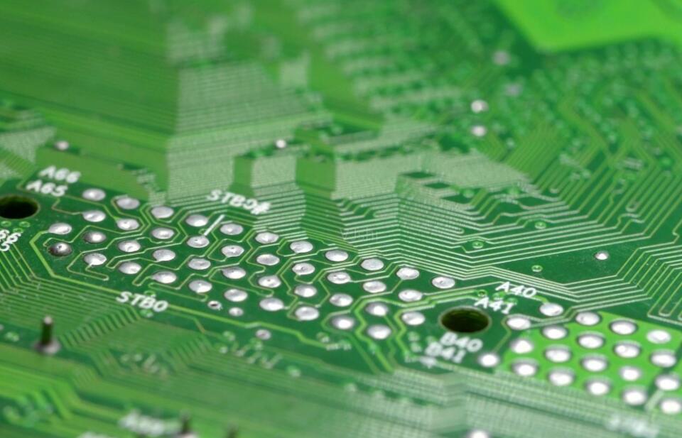
The iron core is provided as a piece of fully cured FR4, with copper plated on both sides. The thickness of the magnetic core is very wide, and the more commonly used sizes are usually stored in a larger inventory. These are the thicknesses you need to keep in mind, especially when you need to order products with fast turnaround, so that you don't waste the delivery time of the order, waiting for non-standard materials to arrive from the distributor.
Common core and copper thickness
The core thicknesses most commonly used to construct 0.062 inch thick multilayers are 0.005 inch, 0.008 inch, 0.014 inch, 0.021, 0.028 inch, and 0.039 inch. 0.047" inventory is also common because it is sometimes used to build 2-layer boards. The other core that will always be stored is 0.059 inches because it is used to produce 0.062-inch thick 2-layer boards, but it can only be used for thicker boards. For this position, we limit the scope to a core design with a final nominal thickness of 0.062 inches.
The thickness of copper ranges from half an ounce to 3 to 4 ounces, depending on the specific manufacturer’s product mix, but most stocks may be 2 ounces or less. Keep this in mind, and remember that almost all inventory will use the same copper weight on both sides of the core. Try to avoid the PCB design requirements that require different copper on each side, because usually this requires a special purchase, may require an expedited fee (expedited delivery), and sometimes cannot even meet the minimum order quantity of the distributor.
For example, if you want to use 1oz of copper on an airplane and plan to use Hoz for the signal, please consider making the airplane at Hoz or increasing the signal to 1oz so that the core is used like copper with weight on both sides. Of course, you can only do this if you can still meet the electrical requirements of the design and have enough XY area to accommodate the widened trace/spatial design rules to meet the 1oz minimum on the signal layer. If you can meet these conditions, it is best to use it like a copper weight. Otherwise, you may need to consider a few days of additional delivery time.
Assuming that you have selected the appropriate core thickness and available copper weight, use various combinations of prepregs to establish the remaining dielectric locations until the required total thickness requirements are met. For designs that do not require impedance control, you can leave the choice of prepreg to the manufacturer. They will use their preferred "standard" version. On the other hand, if you do have impedance requirements, please state these requirements in the document so that the manufacturer can adjust the amount of prepreg between the cores to meet the specified value.
Impedance control
Regardless of whether impedance control is required, it is not recommended that you try to mark the type and thickness of the prepreg at each location in the document, unless you are proficient in this operation. Usually, such detailed stacks eventually need to be adjusted, so they may cause delays. Instead, your stacking diagram can show the core thickness of the inner layer pair, and indicate "prepreg position required based on impedance and overall thickness requirements". This allows the manufacturer to create the ideal stack to match your design.
summary
Ideal stacking of cores based on existing inventory is essential to avoid unnecessary delays during fast turns where ordering times are tight. Most PCB manufacturers use similar multilayer structures based on the same core as their competitors. Unless the PCB is highly customized, there is no magic or secret construction. Therefore, it is worth to be familiar with the preferred material for a specific number of layers and make every effort to design a PCB that matches it. Under special design requirements, there will always be exceptions, but in general, standard materials are the best choice.