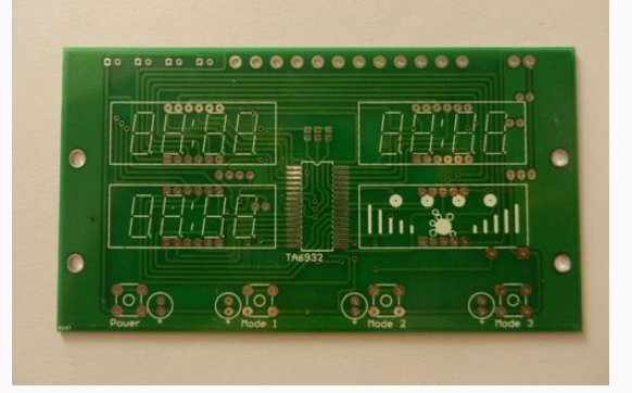
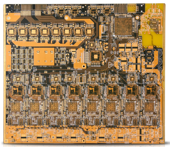
Now more and more circuit boards use surface mount components. Compared with traditional packaging, it can reduce the area of the circuit board, is easy to process in large quantities, and has high wiring density. The lead inductance of chip resistors and capacitors is greatly reduced, which has great advantages in high-frequency circuits. The inconvenience of surface mount components is that they are not convenient for manual soldering.
1. Tools and materials needed for circuit board repair
The soldering tool needs a small 25W copper tip soldering iron. If possible, a soldering station with adjustable temperature and ESD protection can be used. Note that the tip of the soldering iron should be thin and the width of the top should not be greater than 1mm. A pointed tweezers can be used to move and fix the chip and check the circuit. Also prepare fine welding wire, flux, isopropyl alcohol, etc. The main purpose of using flux is to increase the fluidity of the solder, so that the solder can be pulled with a soldering iron, and it can be smoothly wrapped on the pins and pads by the effect of surface tension. Remove the flux on the board with alcohol after soldering.
2. Circuit board repair and welding method
a. Before soldering, apply flux to the pad and process it with a soldering iron to avoid poor tin plating or oxidation of the pad, resulting in poor soldering, and the chip generally does not need to be processed.
b. Use tweezers to carefully place the PQFP chip on the PCB board, taking care not to damage the pins. Make it aligned with the pad and ensure that the chip is placed in the correct direction. Adjust the temperature of the soldering iron to more than 300 degrees Celsius, dip a small amount of solder on the tip of the soldering iron, press down the aligned chip with a tool, and add a small amount of solder to the two diagonal pins, and still Hold down the chip and solder the pins on the two diagonal positions to make the chip fixed and unable to move. After soldering the opposite corners, recheck the alignment of the chip position. If necessary, adjust or remove and realign the position on the PCB board.

c. When starting to solder all the pins, add solder to the tip of the soldering iron, and apply flux to all the pins to keep the pins moist. Touch the end of each pin of the chip with the tip of a soldering iron until you see the solder flowing into the pin. When soldering, keep the tip of the soldering iron parallel to the soldered pin to prevent overlap due to excessive soldering.
d. After soldering all the pins, soak all the pins with flux to clean the solder. Suck off the excess solder where needed to eliminate any short circuits and overlaps. Finally, use tweezers to check whether there is any false soldering. After the inspection is completed, remove the solder from the circuit board, and soak the hard brush with alcohol and wipe it carefully along the pin direction until the solder disappears.
e. SMD resistor-capacitor components are relatively easy to solder. You can put tin on a solder joint first, then place one end of the component, clamp the component with tweezers, and then see if it is placed correctly after soldering one end; Put it right, then solder the other end. To really master the welding skills requires a lot of practice. Now more and more circuit boards use surface mount components. Compared with traditional packaging, it can reduce the area of the circuit board, is easy to process in large quantities, and has high wiring density. The lead inductance of chip resistors and capacitors is greatly reduced, which has great advantages in high-frequency circuits. The inconvenience of surface mount components is that they are not convenient for manual soldering. For this reason, this article takes the common PQFP packaged chip as an example to introduce the method of circuit board repair. Experts answer circuit board repair:
Basic recipes for circuit board repair
An ordinary circuit board, the circuit combination is tens of millions
The appearance of components changes frequently, character recognition is the key
Resistance and capacitance are the most common, damage is also common
The resistance value of the resistance is easy to change, and the leakage of the capacitor is still leaking.
Inductance transformer is a coil, simple test to see the on-off
Diode and triode, measure the positive and negative of the PN junction
MOS tube and thyristor, trigger test is the key
The above are all discrete parts, integrated circuits for many years
The analog device has an op amp, and the virtual short and virtual terminals are used to judge
The optocoupler isolates the front and rear stages, and the damage is tens of millions
Digital devices are often seen, before 40 and 74 marks
There is also an analog-to-digital converter, which is very laborious to test
Don't forget ROM and CPLD, programming depends on the programmer
CPU, single-chip microcomputer, timing judgment logic instrument
A variety of sensors, the probability of damage ranked first