1. The purpose of the experiment
The lead-free reflow of the PCB circuit board will cause the plate to burst, and the copper hole wall of the plated through hole will be broken. The main reason is of course that the CTE of the plate on the Z axis is no matter whether it is α1 (55 -60ppm/ degree Celsius) or α2 (250ppm/ degree Celsius) Z-axis thermal expansion rate (Z-CTE), both far exceed the 17 ppm/ degree Celsius of copper wall. That is to say, the plate material below Tg is about 3 times that of the copper wall, and when the Tg is above it will be pulled up to as much as 12-20 times. In order to prevent the through holes of the multilayer board from being broken and failing during multiple reflows, the temperature cycle test (TCT) is used deliberately to try to find three things, namely
(1) What is the effect of the reflow peak temperature on the plate and through holes?
(2) How many times can be reflowed?
(3) How about the reliability of the base material?
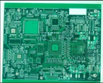
2. PCB circuit board production

A PCB circuit board manufacturer re-used four kinds of boards to fabricate a total of 880 interconnect vias and an 8-layer PCB circuit board with a thickness of 30mm. The copper thickness of the holes was about 20 μm. Before the TCT test, first simulate lead and lead-free reflow with peak temperatures of 224 degree Celsius and 250 degree Celsius respectively, and then perform an air to air temperature cycle test (TCT) to observe the reliability of the plate and plated through holes. The conditions of this TCT are:
.Low temperature-55 degree Celsius for 5 minutes.
. 14 minutes is used as the transition time for high temperature soaring. The reason for deliberately lengthening is to make the inner and outer temperature of the thick plate converge to reduce the stress.
.Place it at a high temperature of 125°C for 5 minutes.
.Transfer to low temperature in 14 minutes and complete one cycle
After a long time of continuous thermal expansion and contraction, the copper crystals such as the copper hole wall and the interconnection ring will become looser, so that the resistance during the DC test will gradually increase. Once the measured resistance value is When it exceeds 10% before the test, it means that the PCB circuit board has reached the point of failure. Then the failure analysis of the microsection can be performed.
Third, the reflow peak temperature has an impact on the reliability of the through hole
When the peak temperature of the reflow is pulled up, it will cause strong thermal stress on the plate and the copper hole wall. Therefore, before conducting TCT reliability tests on plates and through holes, the PCB circuit board was simulated reflow 2 to 6 times to observe the effect of reflow on the subsequent reliability. In the process, it was found that when the reflow peak temperature is increased by 25 degree Celsius, the number of temperature cycles before failure will be reduced by as much as 25%. It really makes people have to be careful about the reflow curve, and try to avoid the peak temperature. Is too high, so as not to cause a lot of troubles.
Fourth, the impact of the number of PCB reflows on the reliability of through holes
In fact, not only the peak temperature of reflow will bring strong stress, but each strong heat of multiple reflow will also accumulate stress in the copper hole wall and the base material. This number of reflow will inevitably degrade the reliability. Therefore, the German investigators deliberately tested the PCB circuit boards with lead-free lead-free reflow for many times, and then carried out the reliability-related TCT test to observe the correspondence between them.
Five, discussion
.The difference in CTE between the copper foil or the copper wall and the base material will be the direct cause of cracks and broken holes after intense heat torture. Increasing the number of reflows will of course shorten the life of the through hole.
.It is found that the main culprit of PCB broken holes is excessively high reflow peak temperature (for example, above 250°C). The secondary factor that affects the reliability of through holes is the number of reflows, and the influence of the first reflow is greater than others The number of subsequent reflows.
.When the copper elongation of the hole is very good (for example, 20z% redundancy or more), the reliability of the through-hole resistance to strong heat will naturally be good, but the elongation will gradually deteriorate after multiple reflows.