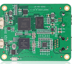
The chip components on the PCB circuit board are a new type of micro-components with no leads or short leads. It is directly mounted on the printed circuit board and is a special part of surface mounting technology. The chip component has the advantages of small size, light weight, high mounting density, high reliability, strong vibration resistance, high frequency characteristics, and strong anti-interference ability. At present, it has been widely used in computer equipment, mobile communication equipment, cameras, color TV tuners, VCD and other products, and has been rapidly developed.
Common chip components are: (1) chip resistors (2) chip capacitors (3) chip inductors (4) chip diodes (5) chip transistors (6) chip-shaped small integrated circuits.
These chip components are very small in size, are resistant to heat, and are not easy to collide. Many pins are difficult to disassemble, which brings great difficulties to maintenance. Therefore, scientific disassembly methods are very important, and the commonly used disassembly methods are as follows.
1. Dedicated tip removal method
Special "Π" prompts are available. The width and length of the notch of the "Π" head can be determined according to the size of the removed part. The special tip can simultaneously melt the solder on both sides of the removed part. It is convenient to delete deleted components. The self-made tip can also be used for disassembly.
Homemade method:
Choose a copper tube whose inner diameter matches the outer diameter of the tip, clamp one end flat or hammered flat with a vise, and drill a small hole, as shown in the figure. Then use two copper plates or pipes to form a horizontal section, the length of which is the same as the length of the part to be disassembled, drill small holes, flatten the end face, polish and clean, and finally assemble them into a shape with bolts and place them on the tip . Hot tin can be used.
For a rectangular chip component with two solder joints, as long as the soldering iron tip is flat and the end face width is equal to the length of the component, the two solder joints can be heated and melted at the same time, and the chip component is deleted.

2, the copper mesh method
Copper-plated copper mesh is a mesh belt woven from thin copper wires, and can also be replaced by metal shielded wires or multiple flexible wires of cables. When in use, cover the network cable on multiple pins, apply rosin alcohol flux, heat it with a soldering iron, and then shake the network cable. The solder on each foot is absorbed by the wire. Cut off the wire for PCB soldering and repeat several times. The solder on the pins is gradually reduced until the pins are separated from the printed circuit board.
3, molten tin cleaning method
When heating multi-leg parts with an anti-static soldering iron, the solder can be cleaned with a toothbrush or paint brush or paint brush, and the parts can be quickly removed. After removing the components, the printed circuit board should be cleaned in time to prevent short circuit of other components caused by residual tin.
4, lead wire breaking method
This method is suitable for removing chip mounted integrated circuits. Use a paint wire of appropriate thickness and strength to pass through the gaps in the IC pins. One end of the enameled wire is fixed in place, and the other end is held by hand. When the solder melts, pull it out. The enameled wire "cuts" the solder joints, and the integrated circuit pins are separated from the printed circuit board.
5, How to disassemble the suction device
There are two types of soldering equipment: ordinary soldering equipment and soldering iron. When using a normal suction device, press down on the piston rod of the suction device. When the soldering iron melts the solder joints of the disassembled parts, close the suction nozzle of the suction device to the melting point, press the release button of the suction device, and then suck the tin. When the piston rod bounces back, the molten tin is sucked away. Iteratively, the removed part can be separated from the printed board. The tin-plated soldering iron is a special soldering tool that can assemble ordinary soldering irons and electric soldering irons. Its use is the same as the amount of traditional PCB solder.