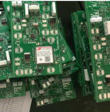
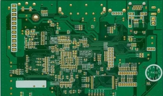
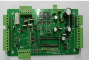
Before mass production, any product needs to go through several proofing processes, or dozens of proofing repeated function confirmations. In this process, what are the basic common sense that the circuit board proofing factory needs to know! 1. When testing PCB boards, Please pay attention to the insulation performance of the electric soldering iron: it is prohibited to use the electric soldering iron for electric welding, to ensure that the soldering iron is not charged, it is best to ground the shell of the soldering iron, pay attention to the MOS circuit, you can use a 6~8V low-voltage circuit iron, which is safer. 2. Understand the working principle of integrated circuits and related circuits before inspecting PCB boards: Before inspecting and repairing integrated circuits, you must first be familiar with the functions of integrated circuits, internal circuits, main electrical parameters, the role of each pin, and the lead The normal voltage of the foot, the working principle of the circuit is composed of waveforms and peripheral components, if the above conditions are met, the analysis and inspection will be easier. 3. It is strictly forbidden to use grounded test equipment to touch the live equipment on the bottom plate to test the PCB board without an isolation transformer: it is strictly forbidden to directly test audio, video and other equipment without power isolation.

The equipment grounded transformer, although common Both radios and cassette tape recorders have power transformers, but when you come into contact with more special TV or audio equipment, especially the output power or the nature of the power source used, you must first determine whether the machine's chassis is installed and charged, otherwise it is very Easily, TVs, audio devices and other devices that are charged with a baseboard will cause a short circuit in the power supply, which will affect the integrated circuit and cause the failure to further expand. 4. The internal resistance of the PCB board test instrument should be large: when measuring the DC voltage of the integrated circuit pins, a multimeter should be used, and the internal resistance of the meter head should be greater than 20KΩ/V. For some pin voltages, the measurement error is relatively large. Big.
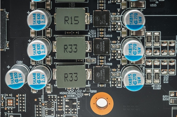
5. Pay attention to the heat dissipation of the power integrated circuit when inspecting the PCB board: the power integrated circuit should have good heat dissipation, and it is not allowed to work at high power without a heat sink. 6. Check the PCB board to ensure the quality of soldering: the soldering speed must be fast, the accumulation of solder and air holes is likely to cause false soldering, the soldering time is usually no more than 3 seconds, and the power of the soldering iron should be about 25W under the condition of internal heating, Check the soldered integrated circuit carefully. It is best to use an ohmmeter to measure whether there is a short circuit between the pins, confirm that there is no solder adhesion, and then turn on the power. 7. The leads of the PCB board should be tested reasonably: if external components need to be added to replace the damaged part of the integrated circuit, smaller components should be selected, and the wiring should be reasonable to avoid unnecessary parasitic coupling, especially audio power amplifiers The ground terminal between the integrated circuit and the preamplifier circuit. 8. When testing the PCB board, do not judge the damage of the integrated circuit easily: do not judge that the integrated circuit is easily damaged. Most integrated circuits are directly coupled. Once the circuit is abnormal, it may cause multiple voltage changes, and these changes may not be Caused by the damage of the integrated circuit, in some cases, when the measured voltage of each pin is different from the normal value, when the value matches or is close, it may not always mean that the integrated circuit is good, some soft The fault will not cause a change in the DC voltage. 9. When testing the PCB board, do not short-circuit the pins: When measuring voltage or using the oscilloscope probe to test the waveform, do not cause a short circuit between the pins of the integrated circuit due to the sliding of the test leads or probes. It is better not to directly connect to the pins on the peripheral printed circuit for measurement. Any instantaneous short circuit may easily damage the integrated circuit. You must be extra careful when testing flat package CMOS integrated circuits.