Double panel/multilayer board/impedance board
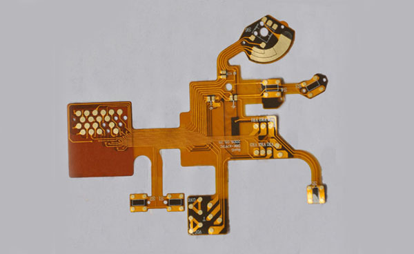
Strictly speaking, the double-sided board is a very important PCB board in the circuit board factory. Its purpose is very large. It is also very simple to see if a PCB board is double-sided. I believe that friends have a complete understanding of single-sided boards. It can be grasped that the double-sided board is an extension of the single-sided board, which means that the circuit of the single-sided board is not enough to turn to the opposite side. The important feature of the double-sided board is the through hole. Simply put, it is double-sided routing, with lines on both sides!
One sentence is: a double-sided wiring board is a double-sided board! Some friends will ask, for example, a board with double-sided wiring, but only one side has electronic parts. Is such a board double-sided or single-sided? Answer Obviously, such a board is a double-sided board, but the parts are installed on the double-sided board!
Second, what is a multilayer circuit board?
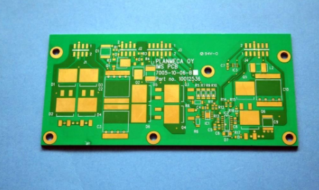
How do you see if a board is a multilayer board? What are the characteristics of a multilayer board, what is a multilayer board, and what are the uses of a multilayer board? Today we will answer the vague concept of a multilayer board in the minds of friends and understand the multilayer board The characteristics of the multi-layer board can be clearly distinguished!

As the name suggests, a multi-layer board is a board with more than two layers. I also told you what a double-sided board is. Then a multi-layer board has more than two layers. For example, four-layer PCB, six-layer, eight-layer, etc., everyone It must be remembered that there are no odd numbers for multi-layer boards, all are multiples of 2. These are basic common sense, everyone should not be funny in future life! Since multi-layer boards are multiples of double-sided boards, they should also have the characteristics of double-sided boards: The conductive trace diagram of a two-layer board is separated by insulating material between layers, and the conductive trace diagram between the layers must be connected according to the circuit requirements. The printed board formed by drilling and pressing and bonding is called multi-layer The advantages of circuit boards and multi-layer circuit boards are that because the conductive wires are multi-layer drilling and pressing, they have high density. Without unfolding, the volume will be smaller and the weight will be relatively lighter. Because of the high density, it reduces the cost of components. Spatial distance is therefore not so easy to break, that is to say, the stability is more reliable, and the number of layers increases the flexibility of design, so as to achieve the purpose of high-speed transmission of circuits with a certain impedance. Because of these advantages, there are relatively some Disadvantages such as high cost, long production time, difficult inspection, etc., but these deficiencies do not affect the use of multilayer boards at all. Multi-layer printed circuits are the direction of electronic technology for high speed, multi-function, large capacity, and small volume. The inevitable product of development. With the continuous development of electronic technology, especially the extensive and in-depth application of large-scale and very large-scale integrated circuits, multilayer printed circuits are rapidly developing in the direction of high density, high precision, and high-level digitalization. Fine lines and small apertures have appeared., Blind and buried holes, high plate thickness to aperture ratio and other technologies to meet the needs of the market. Due to the needs of the computer and aerospace industries for high-speed circuits. The packaging density is required to be further increased, coupled with the shrinking of the size of separate components and the rapid development of microelectronics, electronic equipment is developing in the direction of reduction in size and quality; single and double-sided Due to the limited space available for printed boards, it has been impossible to achieve a further increase in assembly density. Therefore, it is necessary to consider using more printed circuits than double-sided boards. This creates conditions for the emergence of multilayer circuit boards.
Three, what is an impedance board?
I believe that the name impedance board is familiar to many friends who are engaged in circuit boards. So what is an impedance board and what is the function of an impedance board? This will ask many friends who are engaged in circuit boards. Today we will learn what impedance is. What are the characteristics of the impedance board? How do you see if it is an impedance board? The definition of an impedance board is: a good laminated structure can control the characteristic impedance of the printed circuit board, and its wiring can be easily controlled and The predictable transmission line structure is called an impedance plate.
1. Impedance characteristics of printed circuit board
According to the signal transmission theory, the signal is a function of time and distance variables, so every part of the signal on the connection may change. Therefore, determine the AC impedance of the connection, that is, the ratio of the voltage change to the current change as the characteristic impedance of the transmission line (Characteristic Impedance): The characteristic impedance of the transmission line is only related to the characteristics of the signal connection itself. In the actual circuit, the resistance value of the wire itself is smaller than the distributed impedance of the system. In high-frequency circuits, the characteristic impedance mainly depends on the distributed impedance brought by the unit distributed capacitance and unit distributed inductance of the connection. The characteristic impedance of an ideal transmission line only depends on the unit distributed capacitance and unit distributed inductance of the connection.
2, the calculation of the characteristic impedance of the printed circuit board
The proportional relationship between the rising edge time of the signal and the time required for the signal to be transmitted to the receiving end determines whether the signal connection is regarded as a transmission line. The specific proportional relationship can be explained by the following formula: If the length of the wire connection on the PCB board is greater than l/b, the connecting wire between the signals can be regarded as a transmission line. From the signal equivalent impedance calculation formula, the impedance of the transmission line can be expressed by the following formula: In the case of high frequency (tens of megahertz to hundreds of megahertz), it satisfies wL>>R (of course, in the range of signal frequency greater than 109Hz, then Considering the skin effect of the signal, this relationship needs to be carefully studied). Then for a certain transmission line, its characteristic impedance is a constant. The reflection phenomenon of the signal is caused by the inconsistency of the characteristic impedance of the driving end of the signal and the transmission line and the impedance of the receiving end. For CMOS circuits, the output impedance of the signal driving end is relatively small, tens of ohms. The input impedance of the receiving end is relatively large.
3, printed circuit board characteristic impedance control
The characteristic impedance of the wires on the printed circuit board is an important indicator of circuit design. Especially in the PCB design of high-frequency circuits, it is necessary to consider whether the characteristic impedance of the wire is consistent with the characteristic impedance required by the device or signal, and whether it matches. Therefore, there are two concepts that must be paid attention to in the reliability design of PCB design. Tonglian Circuit has been a professional manufacturer of PCB circuit boards for 11 years, dedicated to high-precision double-sided, multilayer circuit boards and impedance circuit board proofing/mass production.
4, printed circuit board impedance control
There are various signal transmissions in the conductors in the circuit board. When it is necessary to increase its frequency in order to increase its transmission rate, if the circuit itself is different due to factors such as etching, stack thickness, wire width, etc., the impedance value will change, making it The signal is distorted. Therefore, the impedance value of the conductor on the high-speed circuit board should be controlled within a certain range, which is called "impedance control". The main factors affecting the impedance of PCB traces are the width of the copper wire, the thickness of the copper wire, the dielectric constant of the medium, the thickness of the medium, the thickness of the pad, the path of the ground wire, and the wiring around the wire. Therefore, when designing the PCB, the impedance of the traces on the board must be controlled to avoid signal reflection and other electromagnetic interference and signal integrity problems as much as possible, and to ensure the stability of the actual use of the PCB. The calculation method of the impedance of the microstrip line and strip line on the PCB can refer to the corresponding empirical formula.
The impedance matching of the printed circuit board is in the circuit board. If there is a signal transmission, it is hoped that it can be transmitted to the receiving end smoothly from the sending end of the power supply under the condition of minimum energy loss, and the receiving end will completely absorb it without doing anything. Any reflections. To achieve this kind of transmission, the impedance in the line must be equal to the internal impedance of the transmitter to be called "impedance matching". When designing high-speed PCB circuits, impedance matching is one of the design elements. The impedance value has an absolute relationship with the wiring method. For example, whether to walk on the surface layer (Microstrip) or the inner layer (Stripline/Double Stripline), the distance from the reference power layer or ground layer, trace width, PCB material, etc. will affect the characteristic impedance value of the trace. In other words, the impedance value can only be determined after wiring, and the characteristic impedances produced by different PCB manufacturers are also slightly different. Generally, simulation software cannot take into account some wiring conditions with discontinuous impedance due to the limitation of the circuit model or the mathematical algorithm used. At this time, only some terminations (Temninators), such as series resistance, can be reserved on the schematic diagram. Alleviate the effect of discontinuity in trace impedance. The real solution to the problem is to try to avoid impedance discontinuities when wiring.
![[Hot spot] PCB manufacturers say they are not worried about orders, but materials are in short supply](/public/upload/image/20210912/e19e03ee3b747407916c98d1a943eb17.png)