PCB factory: how to overhaul the circuit board?
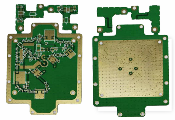
In recent years, the level of automation technology of machinery and equipment has become higher and higher, so the total number of embedded boards in each manufacturing industry is also very large. After the embedded boards are damaged, the huge cost of dismantling and replacing circuit boards has become a headache for companies. One thing. So, do you know what are the repair methods of circuit boards? What is the repair process of circuit boards? Next, let's take a look with the web editor. The classification of circuit boards PCB circuit boards are classified according to the number of superimposed layers, and they are divided into three major categories: single-sided aluminum substrates, double-sided boards, and multi-layer high-rise PCB circuit boards.
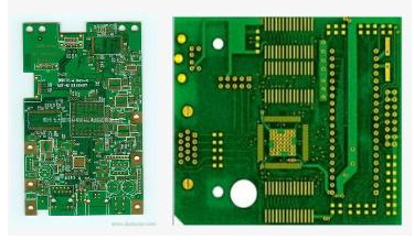
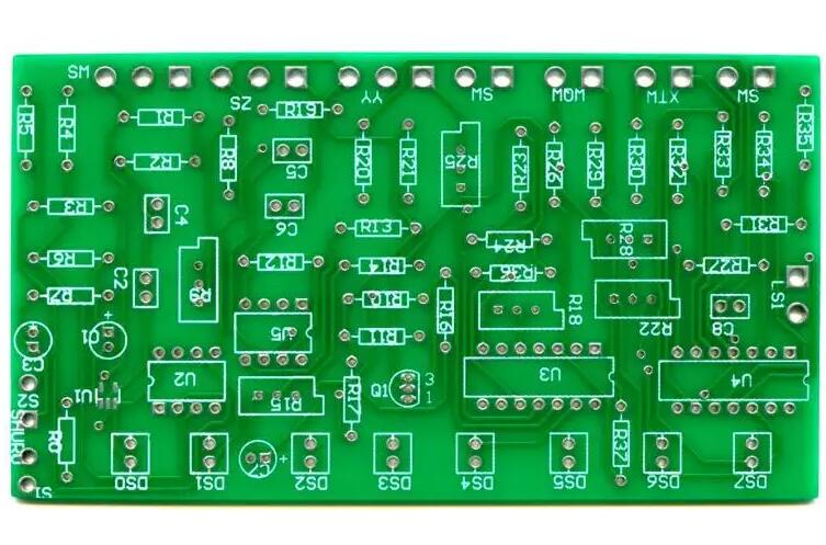
1. Single-sided aluminum substrate, in the most basic
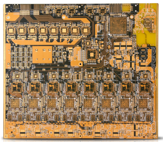
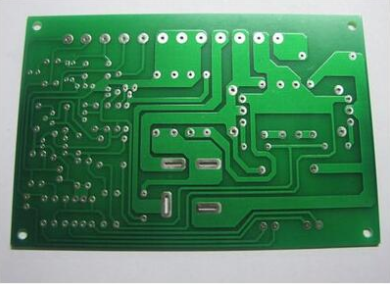
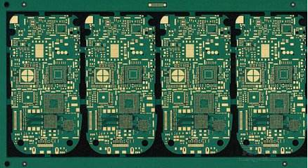
On the PCB, the parts are concentrated on one side, and the transmission lines are concentrated on the other side. Because the transmission line only appears on one side, this type of PCB is called a single-sided PCB circuit board. Single-sided aluminum substrates are generally simple to manufacture and low in engineering cost, but the drawback is that they cannot be applied to too complicated products. 2. Double-sided board is a widening of single-sided aluminum substrate. When single-sided wiring cannot be considered for electronic equipment, double-sided board should be used. There are often copper-clad and wiring on the front and back, and the route between the double layers can be switched on and off according to the via to make the necessary data connection. 3. Solid wood multilayer board refers to a printed circuit board with three layers of conductive pattern layers and insulating layer materials at intervals, and the conductive patterns are interconnected according to regulations. Multi-layer high-rise PCB circuit boards are materials that are trending towards high-speed operation, intelligence, large space, small volume, thinness, and light weight in electronic technology. PCB circuit boards are divided into flexible circuit boards (FPC), rigid boards (PCB), and rigid-soft fusion boards (FPCB) according to their characteristics. The classification of the circuit board The inspection method of the circuit board

1. Needle bed test method This type of method consists of a yellow electrode connected to each detection point on the circuit board. The spring yellow makes each electrode have a working pressure of 100?-?200g? to ensure that each inspection point has good contact. The sorting of such electrodes together is called a "needle bed". Under the control of the mobile phone software for testing, the testing points and testing data signals can be programmed, and the tester can know the information content of all test cases.
2. Observation of the circuit board The circuit board is light in weight and structural analysis, so the observation of the circuit board must also use technical professional observation equipment. Generally, people choose a handheld video microscope to observe the structure of the circuit board. According to the video microscope monitoring camera, a very visualized microstructure of the circuit board can be clearly seen from the optical microscope. According to this kind of method, people can easily carry out the design scheme and inspection of the circuit board.
3. Two-electrode flying probe test method The flying probe tester does not depend on the pin pattern installed on the fixture or support frame. According to this type of system software, 2 or a large number of electrodes are installed on the tiny magnetic heads that can be moved freely on the x-y plan, and the test cases are immediately manipulated by CADI? Gerber statistics. The two electrodes can move within a distance of 4 mils from each other. The electrodes can be moved individually, and there is no real limit to how close they can be to each other. A detector containing two arm-shaped substances that can be moved back and forth should be based on accurate measurement of capacitors. Press the circuit board tightly and place it on the cable sheath on a piece of metal as the other piece of the capacitor. If there is a short-circuit fault in the middle of the route, the capacitor will be larger than at a clear point.
1. Observation When you get a circuit board to be overhauled, you should first observe its appearance carefully. If the circuit board is burned, before plugging in the circuit board, you must carefully consider whether the power circuit is normal, and plug it in after ensuring that it is not easy to cause secondary damage. Observation is a kind of static data inspection method. When applying observation, the following multiple procedures are generally followed.
The first step: observe whether the circuit board is damaged by human factors;
Step 2: Observe whether the electronic components on the circuit board are burnt; Step 3: Observe the integrated circuit chip on the circuit board; Step 4: Observe that the wiring on the circuit board is peeled or burned The condition of coke short circuit. The sinking copper hole has wood to get rid of the pad;
Step 5: Observe the commercial insurance (including fuse tube and thermistor) on the circuit board to see if the fuse is blown. Sometimes, because the fuse is too thin to see clearly, you can rely on the auxiliary software-digital multimeter to tell if the fuse is damaged.
2. Static data measurement method For most of the circuit boards, based on the previous observations, no problems can be found.
If a small part of the circuit board will produce physical deformation due to some unique reasons, and find common faults casually, most of the circuit boards that have common faults must still rely on digital multimeters, and for some key electronic components on the circuit boards., Carry out orderly and accurate measurement in key links, discover and solve problems. Before accurate measurement, it is necessary to distinguish whether the power circuit should be dominated by digital signals or analog signals. The following only mainly discusses the static data measurement method of digital circuits, and the key to maintenance is carried out in accordance with the following many procedures. The first step: Use a digital multimeter to check whether the switching power supply and the ground are short-circuit faults;
The second step: use a digital multimeter to accurately measure the diode, and observe whether everything is normal in its work;
Step 3: Use the resistance profile of a multimeter to accurately measure the capacitor to see if there are short-circuit faults or short-circuit conditions. If yes, it indicates that these power circuits are not good. The next step must be clear whether the components themselves are not good, or follow The power circuit it is connected to is not very good; Step 4: Use a digital multimeter to accurately measure the integrated circuit chips, transistors, resistors, etc. on the circuit board to see if it is in line with its own logical characteristics...Details> > Tips: After inspection based on observations and static data measurement methods, most of the problems in circuit board maintenance can be resolved. One point of special attention is to ensure that everything in the switching power supply is normal to prevent damage to the circuit after the next step. Secondary damage to the board.
3. Automatic measurement method The automatic measurement method is generally used by manufacturers that produce circuit boards in large quantities. For the convenience of inspection and repair, manufacturers will generally build a more general adjustment and maintenance service platform, which can easily show the needs of circuit boards. Switching power supply and some necessary raw data signals. The automatic measurement method mainly deals with two levels of problems.
One is to categorize the problems found in the previous two processes, and finally lock the electronic devices with the problems.
Two is based on the above two steps of inspection, the problem has not been resolved, and the common fault must be found based on automatic measurement. The automatic measurement method is suitable for comparison of two good and bad circuit boards. According to the comparison, problems are found and solved.
a