How to make PCB copy board well in electronic design? The most commonly encountered PCB technology is the grounding of the circuit board, from the most common single analog circuit grounding, simple digital circuit loop grounding to the mixed grounding of analog and digital circuits. These grounding methods all show the development of electronic design. If the product you design has other requirements, such as EMC detection, the circuit board has a higher signal frequency (signal rises to the order of 10ns or lower), then the PCB grounding technology that needs to be considered is also related to these factors at this point Unanimous.
So, today's analysis illustrates the grounding technology under these factors. Before analyzing the grounding technology of the circuit board, we must first understand a reason. Grounding technology is one of the factors that improve the stability of the circuit. In circuit design, reducing loops through various grounding techniques is one of these methods.
Now simply reduce the impact of ground loops on the technology used.

The connection circuit using PCB optocoupler technology is one of the commonly used methods in order to fully protect the back circuit from the influence of the front circuit in the design of the circuit.
In this design, the influence of the transmission circuit on the receiving circuit can be reduced. It is precisely because of the introduction of the optocoupler that the influence of the ground loop on the circuit is greatly reduced.
B. Use isolation transformer technology to connect the circuit. In this method, a 1:1 transformer is used to isolate the transmitting circuit from the receiving circuit.
The ground circuit of the receiving circuit is greatly reduced.
C uses a common mode choke
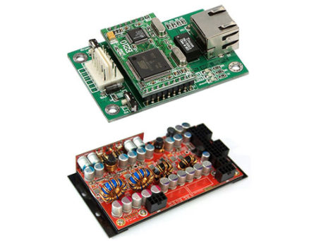
In the circuit design, the receiving circuit is connected to the transmitting circuit through a common-mode choke, which greatly reduces the circuit of the receiving circuit and also provides good technical support for EMC detection. Receiving circuit
D. Using balanced circuit technology. In this method, the transmitting circuit is usually a multi-point parallel power supply, through each circuit equivalent to parallel modules, and finally each module is connected in parallel with a single point grounding.
In a balanced circuit, the current of each module will not affect each other, thereby improving the stability of the system.
After introducing the method of reducing the ground loop, now introduce the method of reducing the grounding in various places.
1. Floating technology In electronic design, one of the commonly used methods is floating technology. This method connects the circuit board signals with the external public to ensure good isolation of the circuit. The circuit is well isolated from the external grounding system and is not easily affected by external system interference, but static electricity is easy to accumulate on the circuit and will cause electrostatic interference, which may generate dangerous voltage.
Small-scale low-speed (<1mhz) equipment can use floating ground (or single-point connection of the working ground to the metal shell), and single-point connection of the metal shell to the ground. Second, series single point grounding = "" This grounding method is recommended by the company's Daniel. Because of its simplicity, there is no need to pay so much attention to the circuit board design, so it will be used more. However, this kind of circuit is prone to common impedance coupling, so that each circuit module affects each other. = ""
Third, parallel single-point grounding = "" This method of grounding, although getting rid of the common impedance coupling problem of series single-point grounding, but in actual use, it will introduce too many grounding wires, as to which one to use, need. In the actual process, if the area of the circuit board allows for a comprehensive evaluation, the parallel mode is used. If the connection between the various circuit modules is kept simple, the series mode is adopted. Generally, there are power modules, analog circuit modules, digital circuit modules and protection circuit modules in the downloaded board. In this case, I use a parallel single-point grounding method. = ""
Fourth, multi-point grounding = "" Multi-point PCB base technology will be used more in daily design, and more used in multi-module circuit design. This grounding method can effectively reduce high-frequency interference problems, but, It is also easy to produce the design problem of the ground loop. This point should be fully considered in the design to improve the stability of the PCB copy board system design. Small high-speed (=""> 10MHz) equipment should be used in conjunction with its metal chassis to achieve multi-point grounding. The connection part should be less than the maximum operating frequency of 1/20 wavelength, and the metal shell should point to the earth at a single point. In short, in electronic circuit design, the most important point is to reduce the circuit area, which plays an important role in improving the stability of electronic design and improving the EMC design of electronic systems. In the actual design, through the comprehensive evaluation of the above-mentioned various technologies, through flexible use, in order to achieve the purpose of improving the stability of the system.