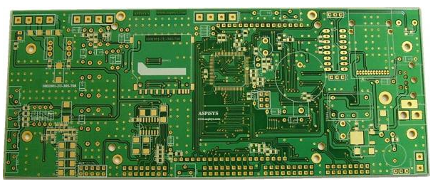
The so-called positioning of CNC milling is to use positioning pins to position the PCB printed board to be processed on the worktable of the milling machine, so as to conveniently and accurately process the shape of the printed board. The positioning is required to be simple and reliable, and the board can be quickly loaded and unloaded while removing the chips. There are many positioning methods. For example, some milling machines are designed with reciprocating worktables. When one workbench is processing, the other workbench loads and unloads plates. There are also two sets of milling positioning pads. When one milling positioning pad is processed on the CNC milling table, the other milling positioning pad is loaded and unloaded on the platform. The exchange of the two takes only a few seconds.
The CNC milling table in PCB proofing itself is a positioning plate, which is an aluminum alloy plate that is positioned by pins and fixed by screws. There is a hole-slot positioning system on the worktable under each CNC milling spindle. The milling pad is actually an intermediate positioning fixture, sometimes called "soft positioning". It is required to be able to locate reliably and quickly unload the board, reduce auxiliary time and improve production efficiency. Before milling the profile, a groove with the same dimensions as the printed board profile is pre-milled on the milling pad. Generally, the dimension of the groove width is the actual machining diameter of the milling cutter plus 0.5 mm. The groove depth is 2.5mm. During the machining process, it is a path of the milling cutter's motion track. As the vacuum cleaner absorbs dust, an air flow is generated in the groove to remove the chips,

make the processed more smooth, prevent the chips from clogging the chip groove of the milling cutter, and reduce the edge. When processing, the milling cutter should be extended into the groove 1.5~2mm. This can prevent the end of the board from being worn out due to the milling cutter continuously cutting into the plate, the diameter is reduced, and the deviation of the printed board processing size due to the reduction of the end diameter allowed by the milling cutter manufacturing.
Before each batch production, the milling backing plate is installed on the CNC milling table, and the new nylon thread plug is screwed on. Drill holes on the threaded plug and install the positioning pin to use. The chip groove on the milling pad is deeper and wider, which will be more conducive to smooth air flow, chip removal, and smoother surface to be machined. However, it weakens the supporting surface, especially when the chip flute is close to the positioning pin, which will make the positioning unstable.
Most of the milling pads in PCB design use non-metal laminates. The material is relatively soft. When the pins are repeatedly loaded and unloaded, the positioning holes are worn and enlarged. For example, semi-specific and consumable milling pads work under such conditions.
Usually, the pin is press-fitted on the milling pad with an interference of 0.005~0.01mm. If it is a special milling pad or a high-density fiberboard is used as a milling pad, a tighter fit is better. However, semi-special milling pads or consumable milling pads, with an interference greater than 0.007mm, may cut off part of the base material in the pin hole to form a deep groove or gap when the pin is press-fitted. With repeated loading and unloading of pins, the pin holes of the laminate also have delamination or chipping. When the printed board is milled, most of the cutting force is borne by the positioning pins. This lateral pressure squeezes the pin holes together with the defects in the holes, which makes the pins loose and deviate one by one. It directly affects the overall dimensions of the printed board, and strict tolerances cannot be guaranteed.
The smaller the diameter of the positioning pin, the greater the relative deflection. Therefore, large diameter holes should be used as positioning holes as much as possible. The locating pin diameter and the amount of deflection also directly affect the productivity. For example, a stack of four pieces was originally scheduled to be milled at one time. Because the pin diameter is small and the amount of deflection is large, then three pieces of milling have to be milled, which reduces the efficiency by 25%.
During the PCB proofing process, the positioning pins should be closely matched to ensure reliable positioning of the processing board. Instead of relying on the help of adhesive tape or adhesive, it takes time to bond and cure. Tight fit also means strict tolerances, and milling multi-layer boards or high-quality double-sided boards can also ensure accuracy.