How to choose circuit materials for different types of radar sensor applications in automotive advanced driver assistance systems (ADAS)
One day in the future, self-driving vehicles will likely be safer than motor vehicles driven by current drivers. But before the driver starts to let go of the steering wheel, some electronic functional components must become standard features of commercial vehicles, including millimeter wave radar systems, cameras and/or lidars. Need a variety of circuit materials. Compared with roads, radar seems to be more easily associated with the battlefield. But it is steadily becoming a very reliable sensor technology, as part of the advanced driver assistance system (ADAS) technology in modern cars to provide electronic safety functions for modern commercial vehicles. The millimeter wave radar system is a mature technology in the automotive industry. As the first active safety function brake assist system, it has been used by Mercedes-Benz since 1996 and is now commonly used in modern ADAS systems. Blind spot detection and anti-collision protection.
Millimeter-wave radars will help autonomous vehicles become possible, but they require a combination of multiple elements, including circuit materials that can provide stable performance for electronic devices and circuits with frequencies above 77 GHz. For example, in ADAS applications, circuit materials require the design of transmission lines that can support microwave and millimeter wave signals at 24,77 (or 79) GHz, to achieve minimal loss, while providing consistent repeatable performance over a wide operating temperature range. Fortunately, Rogers can provide this circuit material with the consistent performance required for ADAS applications ranging from microwave to high-frequency millimeter wave frequency bands.
As part of the electronic perception protection of the vehicle's ADAS system, the vehicle-mounted radar system will be used together with other technologies. Radar systems send electromagnetic (EM) signals in the form of radio waves and receive reflected signals of radio waves from a target (such as another car), which are usually multiple targets. The radar system can extract the corresponding target information from these received reflected signals, including its position, distance, relative speed and radar cross section (RCS). The range (R) can be determined based on the speed of light (c) and the required round-trip time (τ) of the signal. The round-trip time is the time for the radio wave to travel from the radar energy source (radar transmitter) to the target and then return to the radar energy source. In the vehicle-mounted radar system, the occurrence of the radar signal is transmitted to the PCB antenna. The value of R can be obtained by a simple mathematical formula, that is, the product of the speed of light and the round-trip transmission time from the radar signal source to the target and back to the radar source divided by 2: R = cτ/2.
As part of ADAS active safety, the vehicle is equipped with various sensors including cameras, lidar and radar systems
Figure 1: As part of ADAS active safety, the vehicle is equipped with various sensors, including cameras, lidar and radar systems.
When multiple radar targets are relatively close, such as two vehicles in a congested road, precise radar range resolution is required to distinguish the detected objects. A shorter radar pulse can be used to detect a target, although a shorter pulse or any type of signal will reflect less energy from the target back to the radar receiver. More energy can be added to shorter pulses by using pulse compression, where phase or frequency modulation can increase its power level. For this reason, radars based on frequency modulated continuous wave (FMCW) signals (also known as "chirp" signals) are commonly used in vehicle radar systems.
The estimation of the target speed can be achieved through the Doppler effect, which refers to the change in the frequency of the signal reflected by the target obtained from the radar according to the movement of the target relative to the radar transmitter/receiver. The Doppler frequency shift is inversely proportional to the wavelength: according to whether the radar target is close or far away from the radar source, the value is positive or negative.
FMCW or chirp radar system can measure the speed, distance and angle of multiple targets. Although narrow-band (NB) and ultra-wideband (UWB) FMCW radars operating at 24 GHz have been widely used, the application of this frequency band is gradually decreasing. Increasingly, narrow-band 77-GHz radar systems with a bandwidth of 1 GHz are increasingly used in vehicle safety systems. In addition, the automotive industry is studying UWB 79-GHz radar for future applications. CW radar is relatively simple and can detect the speed of the target, but it cannot detect the distance of the target. Pulse continuous wave radar can also use multiple Doppler frequencies to estimate distance. Pulse duration and pulse repetition frequency (PRF) are two key parameters for designing a reliable pulse continuous wave radar system.
Due to pulse compression, the range resolution of FMCW radar is inversely proportional to the bandwidth of the FMCW signal, and has nothing to do with the pulse width. The short-range FMCW radar uses UWB waveforms to measure small distances with high resolution. Doppler resolution is a function of pulse width and the number of pulses used for estimation. The clutter in any radar system is the noise generated by the radar signal reflected by objects other than the target of interest. In any radar system, compared with other surrounding objects, the radar must identify effective targets from many objects illuminated by the radar signal.
The on-board electronic security system uses other physical parameters (such as vision and light) to provide usable data to the vehicle's ADAS domain controller. The domain controller is an information processing center that performs sensor information fusion to help guide the vehicle safely. The front camera is used for lane departure warning and object detection imaging, while the rear camera can provide reverse and additional imaging as needed. Light detection and ranging (LiDAR, lidar) systems transmit pulses of infrared (IR) light to a target (for example, another car or a wall in a parking lot), and detect the IR pulses returning to the source, based on the propagation of light Speed is used to calculate the distance between source and target. Using detailed parameters such as the length and wavelength of the IR pulse and the time required to reflect and return to the IR detector/receiver in the vehicle, the position and relative movement of the IR irradiated object can be calculated. Unfortunately, the performance and effectiveness of vehicle lidar systems are extremely susceptible to severe environmental conditions, such as snow, rain, and fog.
The vehicle-mounted radar system can work in the manner of a LiDAR system, but the corresponding wavelength of the radar of the millimeter wave frequency is smaller. Vehicle-mounted radars are designated for use in certain specific frequency ranges, such as 24, 77 and 79 GHz. These frequency bands have been approved for use by a number of standards organizations, such as the Federal Communications Commission in the United States and the European Telecommunications Standards Institutehave approved their use.
7bbab2ef32f57d3b5c953.png")
Currently, various radars are used as part of ADAS applications, and FMCW signals are widely used due to their effectiveness in measuring the speed, distance and angle of multiple targets. Automotive radars sometimes use narrow-band NB and ultra-wideband UWB designs that operate in the 24GHz frequency band. The 24GHz narrowband vehicle radar occupies the 200 MHz range from 24.05 to 24.25 GHz, and the 24 GHz ultra-wideband radar has a total bandwidth of 5 GHz, from 21.65 GHz to 26.65 GHz. The narrow-band 24 GHz vehicle-mounted radar system can provide effective short-distance traffic target detection and is used for simple functions such as blind spot detection. Ultra-wideband vehicle radar systems have been applied to higher range resolution functions, such as adaptive cruise control (ACC), forward collision warning (FCW) and automatic emergency braking system (AEB).
However, as global mobile communications applications continue to consume spectrum at "lower" frequencies (including 24 GHz accessories), the frequency of vehicle-mounted radar systems becomes higher, and the available millimeter wave spectrum with shorter wavelengths becomes the choice, and the frequencies are respectively It is 77 and 79 GHz. In fact, Japan no longer uses 24-GHz ultra-wideband vehicle radar technology. According to the timetables respectively set by regional standards organizations ETSI and FCC, it will be phased out in Europe and the United States, and will be replaced by higher frequency narrowband 77GHz and ultra-wideband 79GHz vehicle radar systems. The 77GHz and 79GHz radars will be used in some form as functional modules for autonomous vehicles.
Material requirements
Self-driving cars will use many different electronic technologies to provide guidance, control and safety, including sensors that use light and electromagnetic waves. The signal frequency range and circuit technology widely used by millimeter wave frequency radars were once considered unique, experimental, and even only used for military purposes. The increase in the use of millimeter-wave radar is a trend in which more and more electronic technologies and circuits are integrated into motor vehicles, providing convenience and support for drivers, making vehicles safer, and allowing vehicle owners and operators to avoid driving vehicles. Freed from the "task". The use of high-frequency electronics in commercial motor vehicles may even trigger entirely new ways between the driver and the vehicle. At the very least, the use of technologies such as millimeter-wave radar will change the definition of "driving" a motor vehicle.
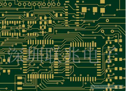
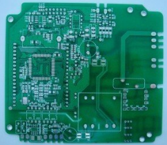
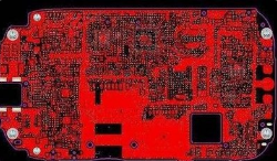
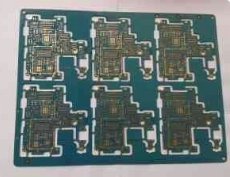
The design of these vehicular millimeter wave radar systems usually starts with an antenna, and the antenna is usually a high-performance printed circuit board (PCB) antenna, which are installed in different positions, By transmitting and receiving low-power milliwatt millimeter wave signals to detect or "illuminate" targets. The vehicle’s radar and other electronic systems use different methods to provide information about the vehicle’s surrounding environment for use by the vehicle’s surrounding object detection and classification algorithms.
The signal of the vehicle-mounted radar may be in the form of pulsed or modulated CW. Vehicle-mounted radar systems have been used for blind spot detection at 24 GHz for some time. However, with the passage of time and the intensification of spectrum competition for other functions such as wireless communication, vehicle-mounted radar systems are moving toward high frequencies and narrowing their bandwidths, such as the 1 GHz wide frequency band centered at 77 GHz and the 79 GHz frequency band.
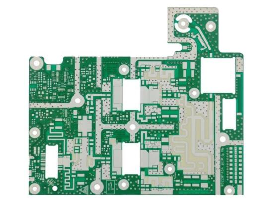
Whether at 24, 77 or 79 GHz, the performance of PCB antennas is critical to these vehicle radar systems. They need to transmit to the target and receive almost instantaneously if the target is a reflected signal from another vehicle. The key PCB antenna performance parameters include gain, directivity and efficiency. Low-loss circuit materials are essential to obtain good PCB antenna performance (Figure 2). The long-term reliability of PCB antennas is also very important, because these compact antennas and their high-frequency transceiver circuits must also continue to work uninterruptedly (when the vehicle is running) and be able to operate in a more challenging operating environment-commercial Motor vehicles-run reliably on top.