Comparison of two PCB board differential TDR test methods
Method one: true bad test method
Step signal A and step signal B are a pair of differential step signals that have opposite directions, equal amplitudes and are issued at the same time.
We not only see the differential step signal on the differential TDR device, but when we observe the pair of step signals with a real-time oscilloscope, we can confirm that this is a real differential signal. Since the TDR step pulse injected into the DUT (device under test) is a differential signal, the TDR device can directly measure the characteristic impedance of the differential line.
Using differential step signals for true differential TDR testing, the greatest benefit to users is that virtual grounding can be achieved.
Since the differential line and the differential signal are balanced, the center voltage point of the differential signal and the ground plane are the same potential, so when the differential step signal is used for differential TDR testing, there is no need to ground as long as channel A and channel B are kept together. You can use DUT.
Method 2: "Superposition" method (pseudo difference)
The step signal A and the step signal B are not hit at the same time, and the directions are not opposite, so the step signal injected into the DUT is not a differential signal at all.

On the screen of this "pseudo-differential TDR" device, it is usually adjusted by manual software, so the step signal we see is emitted at the same time and in the opposite direction. But if we use a real-time oscilloscope to observe these two step pulses, we can see the waveform as shown in Figure 9. We can see the real-time timing relationship between the two step pulses, there is a time difference of 2us.
In other words, these two step signals are not differential signals. Such a TDR step pulse is called a pseudo-differential signal, because it does not actually implement a high-speed differential signal transmission process, that is, the amplitude is equal but the direction is opposite.
Therefore, this method cannot directly measure the differential impedance of the DUT, and can only simulate the differential impedance test by software calculation. On the TDR device, the calculated 2 amplitudes are equal, and the polarity of the opposite step pulse is obtained. The limitation of this differential TDR test is that the simultaneous interaction between differential signals cannot be achieved, and virtual grounding cannot be achieved, and when performing a differential TDR test, the probes of channel A and channel B must have their own independent grounding points.
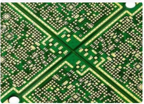
However, the connection location is usually not found near the actual differential line inside the PCB board, which makes it impossible to measure the actual differential wiring inside the PCB board. In order to solve the problem of "pseudo-differential" TDR equipment that is difficult to realize the differential TDR measurement of the actual wiring inside the PCB board, the general PCB manufacturer will make a differential wiring test strip circuit board with the connection position around the PCB, which is called a "coupon". Figure 10 is a typical PCB board, the upper part is the test "coupon", and the lower part is the solid line inside the circuit board. In order to facilitate probe connection, the distance between test points is generally very large, up to 100mil (2.54mm), which greatly exceeds the distance between differential lines.
At the same time, the connection location is next to the test point, and the spacing is also 100mil.
two. Limitations and differences of the "coupon" test
The difference between the test "coupon" and the actual wiring on the board: 1. Although the line spacing and line width are the same, the test point spacing of the "coupon" is fixed at 100mil (the initial value) the pin spacing of the dual-row in-line IC ), which is different from the end of the solid line (ie chip pin) in the board. With the appearance of QFP, PLCC, and BGA packages,
The lead pitch of the chip is much smaller than the pitch of the dual in-line IC package (that is, the pitch of the "sample" test points). 2. The "coupon" line is an ideal straight line, while the solid line in the board is often curved and diverse.
PCB designers and PCB production personnel can easily idealize the "coupon" line, but the actual wiring on the PCB will cause the wiring to be irregular due to various factors. 3. The position of the solid line inside the "coupon" and the entire PCB board is different. The "coupon" is located on the edge of the PCB board and is usually removed by the manufacturer in the PCB board factory.
The actual wiring positions in the circuit board vary, some are near the edge of the circuit board, and some are located in the center of the circuit board.
Because of the third, the "coupon" is different from the solid line on the PCB board position. At present, PCB boards are designed with multi-layer wiring, which needs to be suppressed in production. When the PCB board is pressed, the pressure at different positions on the board cannot be the same, so the dielectric constant of the PCB board at different positions is often different, and the characteristic impedance is of course also different. It can be seen that the TDR test of the "coupon" on the PCB cannot fully reflect the true characteristic impedance of the actual wiring in the PCB. Whether it is a PCB board manufacturer or a high-speed circuit designer, the manufacturer hopes to directly perform the TDR test of the PCB board on the real high-speed differential circuit to obtain the most accurate characteristic impedance information.
The main reasons hindering actual testing are as follows:
It is difficult to find the ground point of a differential TDR probe, and high-speed PCB designers will not set a fixed-pitch ground point line near the end of the line (ie chip pin) when designing high-speed differential.
six. Advantages of TRUE differential TDR test When we discuss the differential TDR test method, we learned that if the step signal sent by the TDR device is a differential signal, virtual grounding can be achieved, that is, the differential TDR detector does not need to be grounded by the PCB board being tested .
As long as there is a differential TDR probe with adjustable spacing in the hand of the tester, the test can be completed. Figure 11 is a differential TDR probe with a bandwidth of up to 18 GHz in the case of differential TDR testing.
Its probe spacing can be adjusted continuously between 0.5mm and 4.5mm, even when testing a test point smaller than the tip of a ballpoint pen, it can be easily completed with one hand. Because the probe has a bandwidth of up to 18 GHz, high test resolution can be obtained, and Figure 12 is the result of testing the differential line "coupon". The red waveform is the initial test result of the "coupon", followed by the small strip on the line (the part shown in the red circle), and then the test is performed to obtain the test result, such as the white waveform. It can be seen that the small impedance discontinuity caused by the sticker is also clearly reflected by the high-bandwidth differential TDR probe. The true differential TDR device has a high-bandwidth differential probe for PCB differential functional impedance testing. There is no need to find the connection position on the PCB board. As long as the probe is adjusted to the appropriate spacing, the real differential wiring can be easily detected in the PCB board.