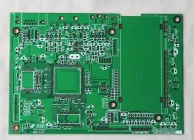
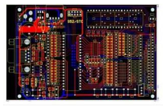
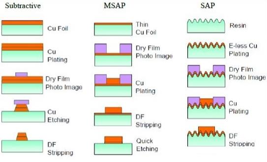
The concept of PCB residual copper rate: The PCB manufacturing process starts with a PCB "substrate" made of glass epoxy (Glass Epoxy) or similar materials. The first step of the production is to lightly draw the PCB design wiring between the parts. The method is to "print" the circuit negative of the designed PCB circuit board on the metal conductor by using a negative transfer (Subtractive transfer) method.
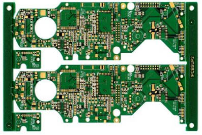
This technique is to spread a thin layer of copper foil on the entire surface and eliminate the excess. And if you are making a double-sided board, then both sides of the PCB substrate will be covered with copper foil. To make a multi-layer board, the two double-sided boards can be "pressed" together with a special adhesive.

Next, the drilling and electroplating required to connect the components can be performed on the PCB board. After drilling by machinery and equipment according to the drilling requirements, the inside of the hole must be electroplated (Plated-Through-Hole technology, PTH). After the inside of Kongbi is metal treated, the inner layers of the circuit can be connected to each other.
Before starting electroplating, the debris in the hole must be cleaned. This is because the resin epoxy will produce some chemical changes after heating, and it will cover the internal PCB layer, so it must be removed first. Both cleaning and electroplating actions are completed in the chemical process. Next, the solder mask (solder mask ink) needs to be covered on the outermost PCB design wiring, so that the PCB design wiring will not touch the electroplated part.
Then, the various components are printed on the circuit board to mark the position of each part. It cannot cover any PCB design wiring or gold fingers, otherwise it may reduce the solderability or the stability of the current connection. sex. In addition, if there is a metal connection part, the "golden finger" part is usually plated with gold at this time, so that high-quality current connection can be ensured when the expansion slot is inserted. Finally, it's the test. To test whether the PCB has a short circuit or open circuit, you can use optical or electronic testing. The optical method uses scanning to find defects in each layer, and the electronic test usually uses a flying-probe to check all connections. Electronic testing is more accurate in finding short circuits or open circuits, but optical testing can more easily detect incorrect gaps between conductors.
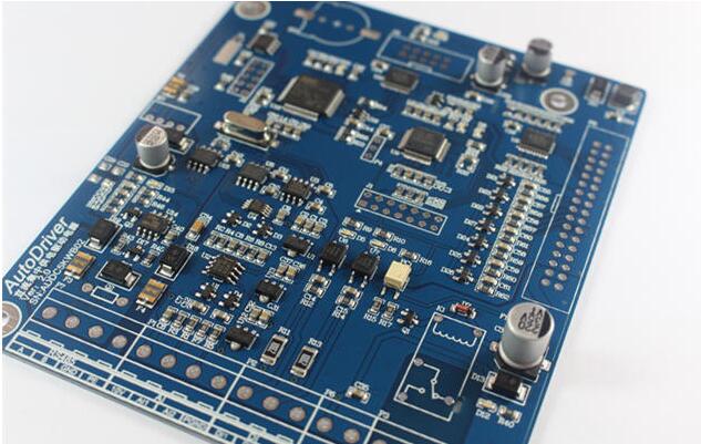
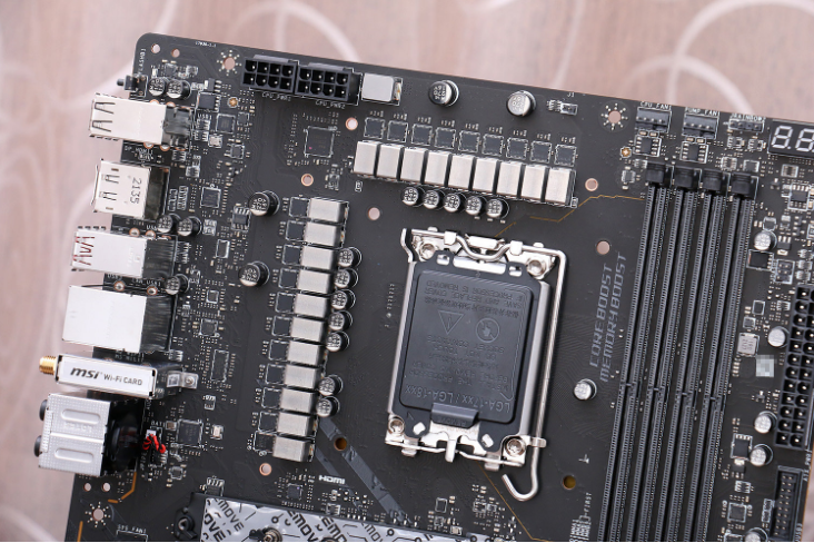
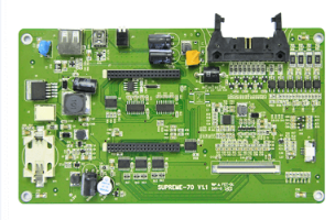
After the circuit board substrate is completed, a finished motherboard is equipped with various large and small components on the PCB substrate according to the needs-first use the SMT automatic placement machine to "sold on the IC chip and chip components, and then manually connect it. Plug in some work that the machine can't do, and firmly fix these plug-in components on the PCB through the wave/reflow soldering process, so a motherboard is produced.
The above is an introduction to the concept of the PCB manufacturing process with regard to the residual copper rate of the PCB.