Crosstalk that should be considered when routing high-frequency circuit board
Editor of PCB electronics factory: With the rapid development of electronic technology and the wide application of wireless communication technology in various fields, high frequency, high speed, and high density have gradually become one of the important trends of modern electronic products. High frequency and high speed digitization of signal transmission Forcing multilayer PCB to move to small holes, buried/blind holes, thin wires and thin dielectric layers. High-frequency, high-speed, high-density multi-layer PCB designtechnology has become an important research area.
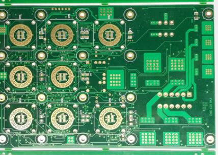
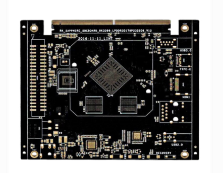
Introduction to high-frequency circuit boards
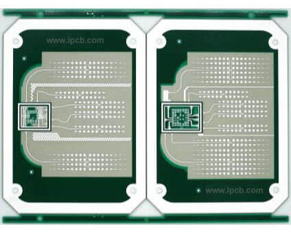
High-frequency circuit boards are special circuit boards with higher electromagnetic frequencies. Generally speaking, high-frequency can be defined as frequencies above 1GHz. Its various physical properties, accuracy, and technical parameters require very high requirements, and are often used in automobile anti-collision systems and satellites. Systems, radio systems and other fields.

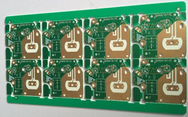
The high-frequency circuit board provided by the utility model is provided with ribs that can block the flow of glue at the upper and lower opening edges of the hollow groove of the core board, so that the core board and the covering placed on the upper and lower surfaces When the copper plate is bonded, the glue will not enter the hollow groove, that is, the bonding operation can be completed by one pressing. Compared with the high-frequency circuit board of the prior art that needs to be pressed twice to be completed, the high-frequency circuit in the utility model The board structure is simple, low cost and easy to manufacture.
Pay attention to the "crosstalk" introduced by the signal lines in close parallel routing
High-frequency circuit board wiring should pay attention to the "crosstalk" introduced by the close parallel routing of signal lines. Crosstalk refers to the coupling phenomenon between signal lines that are not directly connected. Because high-frequency signals are transmitted along the transmission line in the form of electromagnetic waves, The signal line will act as an antenna, the energy of the electromagnetic field will be emitted around the transmission line, and the undesired noise signal generated by the mutual coupling of the electromagnetic field between the signals is called crosstalk., The spacing of the signal line, the electrical characteristics of the driving end and the receiving end, and the signal line termination method have a certain impact on crosstalk. Therefore, in order to reduce the crosstalk of high-frequency signals, the following points are required to be done as much as possible when wiring:
(1) If parallel routing in the same layer is almost unavoidable, in two adjacent layers, the routing direction must be perpendicular to each other;
(2) For high-frequency signal clocks, try to use low-voltage differential clock signals and wrap the ground, and pay attention to the integrity of the ground punch;
(3) When the wiring space permits, insert a ground wire or ground plane between the two wires with more serious crosstalk, which can play a role of isolation and reduce crosstalk;
(4) On the premise of the wiring space permitting, increase the spacing between adjacent signal lines, reduce the parallel length of the signal lines, and try to make the clock line perpendicular to the key signal line instead of parallel;
(5) When there is a time-varying electromagnetic field in the space surrounding the signal line, if parallel distribution cannot be avoided, a large area of "ground" can be arranged on the opposite side of the parallel signal line to greatly reduce interference;
(6) In digital circuits, the usual clock signals are signals with fast edge changes and large crosstalk. Therefore, in the design, the clock line should be surrounded by a ground wire and more ground wire holes are used to reduce distributed capacitance, thereby reducing crosstalk ;
(7) Do not suspend the unused input terminal, but ground it or connect it to the power supply (the power supply is also grounded in the high-frequency signal loop), because the dangling line may be equivalent to the transmitting antenna, and the grounding can inhibit the emission. It has been proved that the elimination of crosstalk in this way can sometimes yield immediate results.