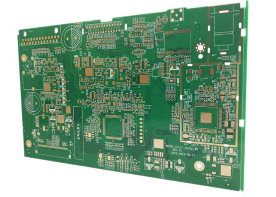
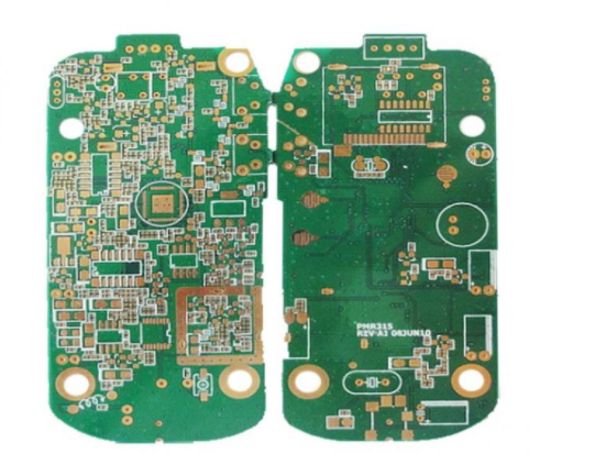
These frequencies were once reserved for the military, when the cost and difficulty of developing millimeter-wave circuits were prohibitions for civilian use. But with breakthroughs in key technologies such as materials and circuits, thousands of millimeter-wave applications have sprung up in 77GHz automotive radar systems, which together with autonomous driving technology are making road travel safer. In order to ensure the optimal working state of millimeter-wave radar system, how to select the most suitable printed circuit board (PCB) material becomes the most critical step in millimeter-wave circuit design process.

Effect of dielectric on Dk
Dk is one of many parameters to be considered when designing circuit board materials suitable for millimeter-wave circuits (such as 77GHz automobile anti-collision radar), and the variation of Dk should be controlled within the range close to its nominal value as far as possible. In addition, other material parameters that can affect the performance of millimeter-wave circuits include: Df, material thickness, copper conductor quality, hygroscopicity, and the "glass braiding" effect caused by glass fiber reinforcement. Again, consistency is essential, especially at millimeter-wave frequencies, where dramatic changes in these parameters can also affect circuit performance.
These different circuit parameters affect the "design Dk" value of the circuit board material. To ensure that the description of Dk is clear and unambiguous, the "effective Dk" here refers to the total Dk value generated during the propagation of the signal. For the microstrip line, "effective Dk" refers to the compound value of Dk in the medium and Dk in the air around the medium. "Design Dk" refers to the Dk value of the material itself on the basis of "effective Dk", that is, the value obtained after eliminating the influence of surrounding air on Dk.

Influence of copper foil on Dk
All components of a circuit board material affect the "design Dk", so consider the parameters of all components of a circuit board. For example, the quality of the copper conductor may affect the performance of the circuit at millimeter-wave frequencies. High quality copper conductors provide high conductivity and consistent impedance for transmission lines, which are key to phase stability at millimeter-wave frequencies, such as in 77GHz automotive radar applications.
The insertion loss of a 50 ω microstrip transmission line from dc to 110GHz was measured to compare the loss characteristics of different copper conductors. The effect of copper surface roughness on conductor loss and insertion loss is obvious (as shown in Figure 4). The thickness of the circuit board material will also affect the loss caused by the rough copper surface. The thinner the material, the greater the influence of the rough copper foil.

How do I keep the Dk stable
Vehicular radars operating at 77GHz can detect small differences in the phase of the reflected signal, and any change in the "design Dk" of the circuit board material will affect the phase state, thereby reducing the detection accuracy of the system. Ideally, you want the Dk value of the circuit board material to remain unchanged under any conditions. But the reality is that the "design Dk" of a material can change depending on various factors such as frequency, temperature and thickness. Only when the maximum tolerance of the INTRINSIC circuit material Dk value is controlled within the range of ±0.05 can the phase fluctuation not affect the high accuracy and high reliability of the system.
Some PCB materials based on THE PTFE resin system have a steep change in Dk values at room temperature (around 25°C). For most applications, TCDk can be controlled in the range of 0±25ppm/°C. Taking RO3003 circuit board material as an example, when the temperature changes from -50 to 150°C, the TCDk in the z-axis direction at 10GHz frequency is only -3ppm /°C. The smaller the TCDk, the less the Dk changes with temperature (see Figure 5), which is critical for millimeter wave frequency applications and for circuits that need to maintain stable performance over a wide temperature range.

For 77GHz radar, if the PCB material with strong "glass braiding effect" is selected, it may be affected by group delay, propagation delay and phase Angle change. In order to ensure the phase stability, the circuit board material with "uniform open fiberglass braided" as the filler should be selected for the 77GHz circuit, and the Dk variation of the circuit board material should be as small as possible. If a circuit board material with "interwoven open glass broughs" is used as a filler, the Dk value will change by about 0.09 at 77GHz, resulting in a phase difference of about 100 degrees. The phase Angle changes greatly, which means that the group delay and propagation delay of the circuit of these materials will be greatly different. Ideally, a fiberglass-free material, such as RO3003 or RO3003G2 laminates, can be used to avoid the "fiberglass effect".

In order to evaluate the effect of different circuit board materials and copper conductor types on the circuit, it takes a lot of time and effort to use full-wave electromagnetic field simulation software to simulate the circuit, or to directly process the real thing for testing. A simpler approach is to use mWI-2019, a free software program based on Microsoft's Windows platform. The software can be downloaded for free from the Official Rogers web site. The software (see "More on MWI-2019") allows users to use its built-in database to verify the effect of material thickness, copper conductor surface roughness, and other parameters on the "Design Dk". The database also contains "Design Dk" values for many other different materials. While the software provides slightly less precise results, its computational time is much faster than that of full-wave electromagnetic simulation software, providing almost immediate initial values for different materials and material parameters used in millimeter-wave circuit board.