The path to build an economically viable 5G over the air (OTA) test scenario is not very clear. As 5G standard development, network deployment and equipment manufacturing are under tremendous pressure, we have not yet been able to solve related practical problems through the 5G OTA test system. This article discusses some of the challenges faced and discusses some possible solutions.
The new radio (NR, new radio) technology has become a package solution to all current wireless communication requirements, including achieving high throughput, low latency, and improving the quality of service (QoS, quality of service) for end users. ) And quality of experience (QoE, quality of experience). The primary task is to meet the exponential growth of user and service capacity in mobile broadband communications. Global mobile traffic will surge from 7,201 gigabytes per month in 2016 to approximately 48,270 gigabytes per month in 2021, a growth rate of 670%. 1 NR is also expected to be used to handle the massive amount of devices connected to IP networks, the number of which will be approximately three times the global population in 2021 (also increasing from 2.3 network devices per capita in 2016 to 3.5 per capita in 2021). The key features of 5G also include 99.999% perceived availability and ultra-reliability, which increases complexity.
In the process of various companies competing to achieve growth, connectivity, availability and reliability, 3GPP and CTIA have emerged as a standards-making organization, enabling new technologies to be fully OTA tested before large-scale deployment. Based on the past experience of 4G OTA test standardization, the key question is what can be achieved by the consensus-based OTA test standardization process and how it can be used to solve the practical challenges in 5G deployment and operation. With the emergence of new 5G concepts such as MIMO technology, beamforming, and widely used millimeter wave frequency bands, 5G OTA testing has become the biggest challenge in the wireless communication industry in the past decade, and it is also a key milestone for the successful realization of 5G deployment and operation.
5G OTA test method

The 3GPP TR 38.810 protocol discusses the antenna configuration of three different 5G device under test (DUT, device under test) and several 5G OTA test methods, which are summarized in Table 1. Among them, the Reverberation Chamber (RC) method is very suitable for measuring isotropic Key Performance Indicators (KPI), especially the total radiated sensitivity (TIS) and spurious emissions. Recent research results have realized the ability of directional measurement through time reversal or Doppler recognition effect2, as shown in Figure 1. At the same time, people are also developing some new uses of reverberation rooms for 5G OTA testing, especially for equipment 3 in a directional channel environment and real-time OTA testing of throughput and delay.
The reverberation room method has some positive effects on 5G non-standalone (NSA, Non-Standalone) and independent (SA, Standalone) OTA testing. For example, when it is used to solve complex multi-carrier requirements, it is greatly reduced compared with other solutions. Setup cost. Although the complex multipath system means that some spatial information may be lost, it is enough to make up for the delay and total throughput performance in 3D isotropic simulation. After all, the latter is the user can perceive in a reasonable time slot. of. However, 5G OTA has made little progress in applying the reverberation room method for isotropic 5G channel model simulation. At the same time, because the reverberation room method lacks strong support in 3GPP, it is not yet a 5G standardized test method.
The expansion of multiprobe anechoic (MPAC) to 5G means the need to introduce 3D channel models and millimeter waves, which greatly increases the complexity and the number of required detectors and supporting channel simulator ports, which greatly affects the already reduced Quiet zone, so the scheme lacks feasibility. Although some researchers have proposed some simplified partitioned variants of the multi-probe method, they need to be operated in the far field. This additional requirement at least limits the application of the multi-probe method to 5G OTA in the millimeter wave frequency band.
Incorporating Radiated Two-Stage (RTS) into the process of standardized 5G OTA testing, thanks to the obvious coordination of the multi-probe method using 7 4G LTE FDD devices in a single 2*2 single-carrier MIMO OTA mode, However, the antenna characteristics of the "wireless cable" of the device under test are not clear, and these characteristics must be measured in advance before this method can be applied. In addition, the two-step method is temporarily unable to support 5G user equipment (UE, user equipment) to use the beam lock test function (UBF), which is obviously a limiting factor for standardized OTA testing. On the other hand, the electrical size of the device under test is only affected by the size of the test chamber.
With the help of a reflector, the Indirect Far Field (IFF) Compact Antenna Test Range (CATR) method can create a plane wave field in a smaller space than the Direct Far Field (DFF) method. It seems to be very suitable for 5G millimeter wave OTA testing, but it cannot provide different frequency bands. Based on the current situation, the CTIA committee recently decided to give special consideration to the IFF law during the drafting of the CTIA 5G NSA millimeter wave OTA test plan v1.0, version 4 to be released in the second quarter of 2019.
The near-field-to-far-field (NFTF) method uses mathematical transformations to determine the far-field KPI from the near-field pattern scan. The NFTF method has flaws when testing actual equipment in operation. Initially, the NFTF test system was used to measure equivalent isotropic radiated power (EIRP, Equivalent Isotropic Radiated Power) and total radiated power (TRP, Total Radiated Power).
The DFF method needs to know the Fraunhofer far-field distance, which is not possible in the millimeter wave frequency band in view of space and cost requirements and link budget. It can be seen from Fig. 2 that as the size of the array increases, the far field range of a set of N*N arrays with a half-wavelength spacing also increases significantly. However, the hybrid application of DFF may be very useful for the 5G sub-6GHz frequency band, because other methods have exposed shortcomings at such low frequencies.
Obviously, there is currently no single OTA method that can solve all the challenges faced by 5G testing. In response to the many problems faced by 5G OTA, some companies and institutions are calling for the development of new or hybrid test methods to effectively deal with them. The recently released CATR+DFF+SNF 5G OTA test system is a good choice, as shown in Figure 3. An optimized special reflector design can cover the millimeter wave area (FR2 frequency band) and part of the sub-6 GHz area (FR1 frequency band), and a hybrid DFF/SNF tower ensures that FR1+FR2 OTA testing is carried out at the same time.
Challenges of 5G OTA testing
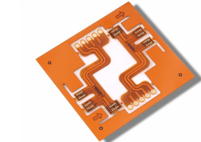
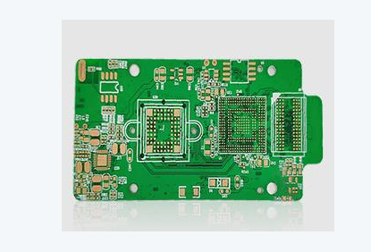
Fully integrated antenna array
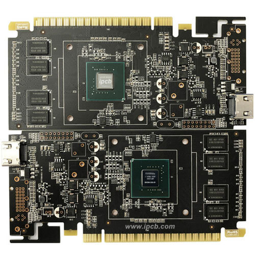
Different from previous generations, 5G user equipment is not only filled with dense antennas as shown in Figure 4, but also not connected to other radio frequency ports because of its small size and high frequency in some frequency bands. Testing antenna arrays without connectors is obviously a difficult problem, requiring us to perform OTA radio frequency testing and calibration in a strictly controlled environment. In addition to signaling performance testing and power measurement, phase calibration between links is usually required. The possible coupling and the limitation of the shape of the test object result in the coherent calibration of each RF link not necessarily forming the optimal beam. The up-down conversion of the millimeter wave frequency band also makes the detection equipment more complicated.