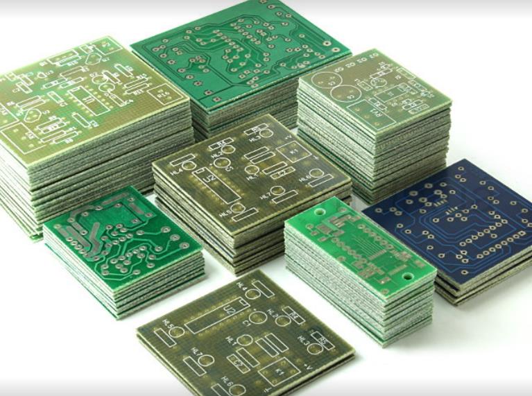
High density interconnector (abbreviated as HDI) is a new era PCB, and its wiring density is higher than that of standard PCB Design. These plates are characterized by buried/blind holes and micropores with a diameter of 0.006, high-performance thin materials and fine wires. Today, these HDI PCB are used in a variety of industrial applications that require perfect board operation. This article discusses the factors that make HDI one of the fastest growing PCB technologies.
1. Introduction to HDI PCB Microwells
The increased wiring density on HDI PCB allows more functions per unit area. The advanced HDI PCB has stacked micro holes filled with multi-layer copper, which can realize complex interconnection. Microholes are tiny laser drilled holes on multilayer circuit boards that can be interconnected between layers. In advanced smartphones and handheld electronic devices, these pores span multiple layers. Microholes are through holes in the pad that are staggered, offset, stacked, copper plated on the top, plated, or filled with solid copper.
2. Type of HDI PCB board
HDI boards are mainly divided into three types:
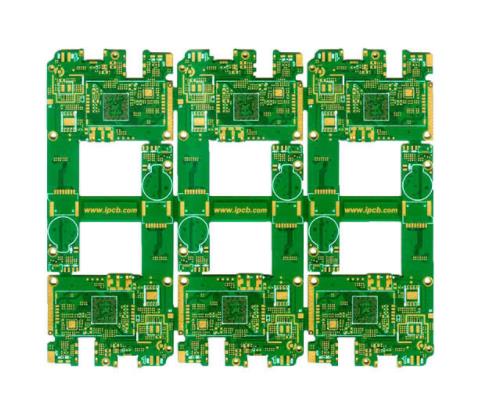
HDI PCB (1+N+1): These PCBs have a "stacked" high-density interconnect layer. This type of

PCB Design has excellent stability and installation. Popular applications include mobile phones, MP3 players, UMPC, GPS, PMP and memory cards.
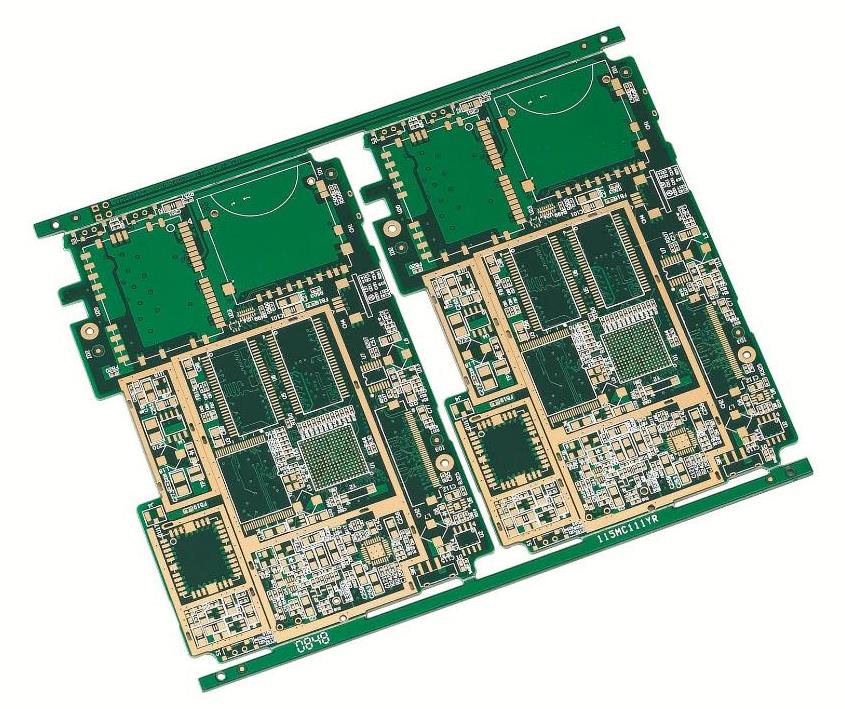
HDI PCB (2+N+2): These PCBs have two or more "stacks" on the high-density interconnection layer. Micropores are interlaced or stacked on different layers. The PCB has a thin plate function. Lower Dk/Df materials can provide better signal performance. Popular applications include personal digital assistants (PDAs), mobile phones, portable game consoles, camcorders and differential scanning calorimeters (DSC).
ELIC (each layer of interconnection): These PCBs have all high-density interconnection layers, so that conductors can be freely interconnected through stacked micropores filled with copper. These PCBs have excellent electrical characteristics. Popular applications include GPU chip, CPU, memory card, etc.
3. Advantages of HDI PCB
HDI PCB is considered to be a perfect substitute for sequential laminates or expensive standard laminates for high layers. The following advantages illustrate their popularity.
4. About laser pore forming: the blind hole of HDI mobile phone board is generally about 0.1mm micro hole. Our company uses CO2 laser. The organic material can strongly absorb infrared rays and ablate into holes through thermal effect. However, the absorption rate of copper to infrared rays is very small, and the melting point of copper is high, so CO2 laser cannot ablate copper foil, so we use the "consistent mask" process, Etch the copper sheet of laser drilling hole with etching solution (CAM needs to make exposure film). At the same time, in order to ensure that there is copper sheet in the secondary outer layer (bottom of laser drilling), the spacing between blind holes and buried holes should be at least 4mil. Therefore, we must use Analysis/Fabrication/Board Drill Checks to find out the hole locations that do not meet the conditions.
5. Plug hole and resistance welding: In HDI laminating configuration, the secondary outer layer is generally made of RCC material, with thin medium thickness and small glue content. According to the process experiment data, if the thickness of finished plate is greater than 0.8mm, the metallization groove is greater than or equal to 0.8mmX2.0mm, and the metallization hole is greater than or equal to 1.2mm, two sets of plug hole documents must be made. That is to say, the plug hole is divided into two times.
The inner layer is leveled with a resin, and the outer layer is directly plugged with solder mask ink before solder mask. In the process of resistance welding, vias often fall on or close to SMD. The customer requires that all vias be plugged, so when the solder mask is exposed, the vias with solder mask exposed or half of the holes exposed are easy to leak oil. CAM staff must deal with this. Generally, we prefer to remove the vias. If the vias cannot be removed, follow the steps below:
1. Add a light transmission point 3 MIL smaller than the one side of the finished hole on the solder mask layer at the through hole position of the covered window.
2. Add a light transmission point 3 MIL larger than one side of the finished hole on the solder mask layer at the through hole position of the solder mask opening touch. (In this case, the customer allows a little ink pad)
In the CAM production of all kinds of PCB Design, the personnel engaged in the CAM production agree that HDI mobile phone PCB boards have complex shapes, high wiring density, and the CAM production is difficult to complete quickly and accurately! In the face of the requirements of customers for high quality and fast delivery, I have learned a little from my continuous practice and summary, and I would like to share this with my CAM colleagues.