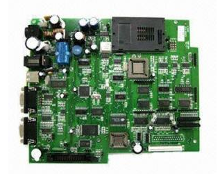
According to the sample BOM placement location map provided by the customer, perform the program for the coordinates of the placement component. Then the first piece is matched with the SMT patch processing data provided by the customer.
Ointment
The solder paste is printed on the pads of the PCB board with a stencil to prepare for the soldering of the components. The equipment used is a screen printing machine (printing machine), located at the forefront of the SMT patch processing production line.
Patch
Install the electronic components SMD accurately on the fixed position of the PCB. The equipment used is a placement machine, located behind the screen printing machine in the SMT production line. Mounting machines are divided into high-speed machines and general-purpose machines.
High-speed machine: used to paste components with large and small lead spacing.
General-purpose machine: paste small pin spacing (pin dense), bulky components.

Melting solder paste
The main purpose is to melt the solder paste at high temperature, and after cooling, make the electronic components SMD and PCB board firmly welded together. The equipment used is a reflow oven, which is located behind the placement machine in the SMT production line.
Cleaning
Its function is to remove the solder residues such as flux that are harmful to the human body on the assembled PCB board. The equipment used is a washing machine, and the location may not be fixed, it may be online or offline.
Visual inspection
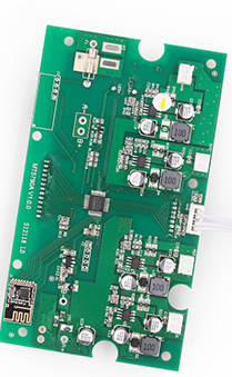
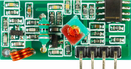
The key items of manual inspection: whether the PCBA version is the changed version; whether the customer requires components to use substitute materials or components of designated brands and brands; IC, diodes, transistors, tantalum capacitors, aluminum capacitors, switches, etc. Whether the direction of the directional components is correct; Defects after welding: short circuit, open circuit, fake part, fake welding.
Package
The assembly method of SMT and its process flow mainly depend on the type of surface mount component (SMA), the types of components used and the conditions of assembly equipment. In general, SMA can be divided into three types of single-sided mixed assembly, double-sided mixed assembly and full-surface assembly, a total of 6 assembly methods. Different types of SMA have different assembly methods, and the same type of SMA can also have different assembly methods.
Choosing an appropriate assembly method according to the specific requirements of the patch processing and assembly products and the conditions of the assembly equipment is the basis for efficient and low-cost assembly and production, and it is also the main content of the SMT process design.
1. The first type is single-sided mixed assembly, that is, SMC/SMD and through-hole plug-in components (17HC) are distributed on different sides of the PCB, but the welding surface is only one-sided. This type of assembly method uses single-sided PCB and wave soldering (currently double wave soldering is generally used). There are two specific assembly methods.
(1) Paste first. The first assembly method is called the first-attach method, that is, the SMC/SMD is attached to the B side (welding side) of the PCB first, and then the THC is inserted on the A side.
(2) Post-sticking method. The second assembly method is called post-attachment method, which is to first insert THC on the A side of the PCB, and then mount the SMD on the B side.
The second type is double-sided hybrid assembly. SMC/SMD and THC can be mixed and distributed on the same side of the PCB. At the same time, SMC/SMD can also be distributed on both sides of the PCB. Double-sided hybrid assembly adopts double-sided PCB, double wave soldering or reflow soldering. In this type of assembly method, there is also a difference between SMC/SMD or SMC/SMD. Generally, it is reasonable to choose according to the type of SMC/SMD and the size of the PCB. Usually, the first method is more adopted. Two assembly methods are commonly used in this type of assembly.
(1) SMC/SMD and FHC on the same side. SMC/SMD and THC are on the same side of the PCB.
(2) Different side modes of SMC/SMD and IFHC. Put the surface mount integrated chip (SMIC) and THC on the A side of the PCB, and put the SMC and small outline transistor (SOT) on the B side.
In this type of assembly method, the SMC/SMD is mounted on one or both sides of the PCB, and the leaded components that are difficult to be surface-assembled are inserted into the assembly, so the assembly density is quite high.
3. The third type is full-surface assembly, with only SMC/SMD on the PCB and no THC. As the current components have not yet fully realized SMT, there are not many such assembly forms in practical applications. This type of assembly method is generally assembled on a PCB or ceramic substrate with a fine line pattern, using fine pitch devices and reflow soldering processes. It also has two assembly methods.
(1) Single-sided surface assembly method. Single-sided PCB is used to assemble SMC/SMD on one side.
(2) Double-sided surface assembly method. Using double-sided PCB to assemble SMC/SMD on both sides, the assembly density is higher.