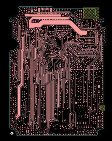
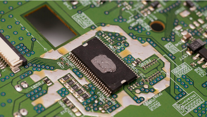
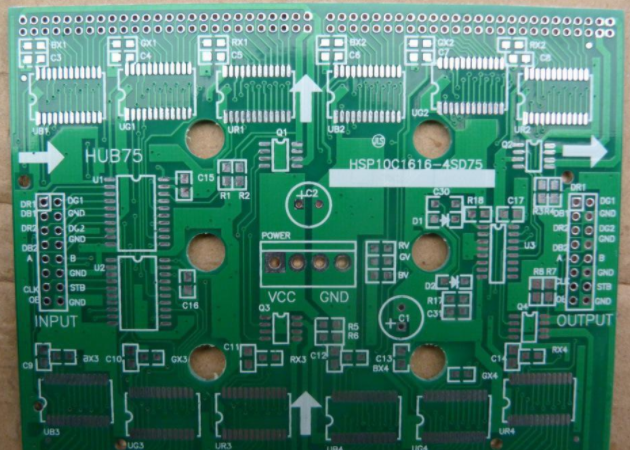
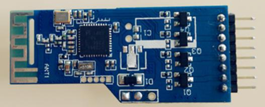
The SMT placement machine is also called the placement machine. The placement machine is a technical comprehensive equipment composed of a rack, a transmission system, a vision system, a computer program and hardware. The placement machine is used to mount electronic components to a PCB (circuit board) In the electronic processing equipment, the densely packed electronic components on the motherboard in the electronic equipment used are all made by the placement machine and then reflow soldering. Then how are the electronic components mounted by the placement machine? The placement machine has a very important component called the nozzle, the English name is nozzle, the placement head of the placement machine is like our arm, and the chopsticks are like the suction nozzle, let’s introduce the knowledge of the suction nozzle. .

The placement machine supplies electronic components to the placement head through a feeder, which is covered with suction nozzles of various sizes and shapes to absorb different electronic materials. The placement machine is like a person eating, then the feeder is like a bowl, the nozzle is like a chopstick or a soup spoon, and the smt placement head is like a human hand. The placement machine completes the placement work through these three components.
The number of nozzles of different brands and models of placement machines are different, but they are roughly divided into the following types
Nozzle classification: high-speed head and general-purpose head
1. The high-speed head is mainly used to absorb relatively small components: such as 0201,0402
2. The general-purpose head mainly absorbs relatively large components or some heterogeneous components, and the mounting speed of the general-purpose head is generally slow
Nozzle shape:
The nozzle shape has square hole, round through, V groove
Custom-made nozzles, according to the shape of the electronic component material, choose a flat suction point to make an elongated nozzle, stretch the groove surface of the material to suck, according to the edge of the material, make it into a back shape, use at both ends Flat, irregular in the middle
Nozzle material:
1. Tungsten steel nozzle: The tungsten steel nozzle is strong and durable, but it is easy to turn white. If it becomes white, use an oil-based pen to paint, and you can continue to use it.
2. Ceramic nozzle: The ceramic nozzle is never white, but it is brittle and easy to break. Careful use can avoid or reduce the occurrence of breakage.
3. Diamond steel nozzle: strong, easy to use, never whitish, but extremely expensive and not cost-effective.
4. Plastic nozzle: When the surface of the material is uneven or the material is sticky, it is suitable to choose the plastic nozzle, but the life of the plastic nozzle is not long. It is recommended to buy more plastic nozzles for spare when ordering the plastic nozzle. When the tip of the mouth is worn out, you can just replace the tip of the glue yourself.
The working principle of the nozzle of the placement machine
The suction nozzle of the placement machine adopts a visual centering system
The vision centering system uses digital image processing technology. When the nozzle on the placement head picks up the component, it is moved to the placement position by a camera fixed on the placement head or fixed on a certain position of the fuselage. To obtain the image, the nozzle of the smt mounter passes through the optical density distribution of the image detection element. These optical densities pass through the CCD optocoupler array composed of many small and precise photosensitive elements on the camera in digital form, and output the gray value of 0-255. The gray value is directly proportional to the optical density. The larger the gray value, the clearer the digital image. The digital information is stored, encoded, amplified, sorted and analyzed, and the result is fed back to the control unit, and the processing result is output to the servo system to adjust the position deviation absorbed by the compensation component, and finally complete the patch operation.