The difference between 5G high frequency and millimeter wave, as well as the changing ways of PCBs in the 5G industry, and the types of PCB various purposes.
What is the next generation communication standard "5G"?
There are three main changes in 5G:
1. Multiple simultaneous connections;
2. Ultra-high speed and large capacity;
3. Low latency.
Compared with 4G, the communication speed is 20 times, the delay is 1/10, and the number of simultaneous connections is 10 times. (The communication speed of 4G is 15 times that of 3G)
5G is too fast for previous standards. The key is that large-capacity communications and multiple connections can be completed without delay. This will make telemedicine possible, provide high-definition VR games and movies, and combine a large number of sensor information and image processing functions to realize autonomous driving and smart cities.
High frequency and the difference between 5G and millimeter wave
The frequency band used for 5G communication and the frequency band called millimeter wave are both high frequency. The frequency band used in 5G is divided into Sub6 and millimeter wave. Sub6 is a frequency band less than 6 GHz, which can be achieved by applying the same communication technology as 4G (LTE, Wi-Fi). However, in the Sub6 frequency band, the ultra-high-speed, high-capacity communication has not improved significantly.
The characteristics of ultra-high speed and large capacity are attributed to the characteristics of the millimeter wave band.
Generally, millimeter waves are frequencies exceeding 30 GHz, but since the 5G communication band of 28 GHz is close to millimeter waves, it is indiscriminately called millimeter waves.

Replacement materials for high-frequency substrates
In order to meet the millimeter wave range, the dielectric loss of the insulating material must be reduced. Dielectric loss refers to the loss of energy as heat when an AC electric field is applied to a dielectric, which leads to signal degradation. Especially in the millimeter wave region, the influence of signal degradation caused by dielectric loss is great, so the selection of the insulating material of the circuit board is very important.
Fluorocarbon resin is a representative resin with low transmission loss, and Teflon and polytetrafluoroethylene are famous. It has excellent heat resistance, moisture resistance, and chemical resistance, but it is too hard and poor processability during PCB manufacturing.
LCP (Liquid Crystal Polymer) is another material with low transmission loss, but its disadvantage is that it has high thermoplasticity and defects due to high temperature processing of PCB during board manufacturing.
Currently, every company is developing resin materials with low transmission loss in the millimeter wave region.
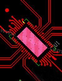
Even if it is a product that supports high frequency, it is not necessary to use the above introduced materials with low transmission loss to manufacture the insulating layer of the entire printed circuit board. There is a method in which only a high-frequency circuit layer or only a part of an RF module that emits radio waves is used as a substrate for transmission loss.
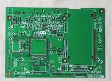
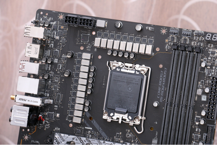
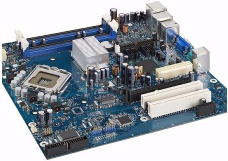
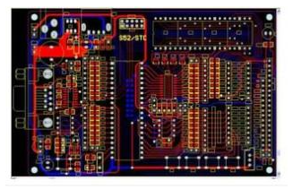
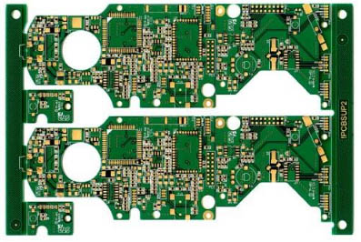
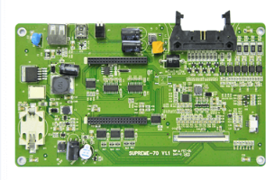
What is the board used for 5G communication?
The circuit board is used in the PCB base station to send and receive 5G radio waves. Most base station boards are high-throughput through-hole boards with multiple insulating layers and pattern layers. The RF module for 5G communication is installed in 5G smartphones and surveillance sensors, and the board usually has the specifications of any laminate with ultra-high density. Most radars used for autonomous driving have relatively large composite board specifications.