The quality of PCB copper foil substrates is becoming more and more stringent with the trend of electronic systems that are lighter, thinner, shorter, higher function, higher density and higher reliability. PCB copper foil substrate manufacturing, inspection specifications from raw material glass fiber cloth, film baking conditions, glue content, glue flow, gelling time, conversion degree and storage conditions, etc., the setting of substrate pressing conditions will all affect PCB copper foil substrate thickness quality, thickness quality control, it is necessary to review all the manufacturing processes, and make a certain degree of improvement in the process capability, instead of blindly selecting and increasing costs. At present, PCB copper foil substrate manufacturing plants have gradually switched to non-contact laser thickness measurement instead of manual inspection of thickness by sub-centimeter cards. The system design has its own characteristics. Most of the laser thickness gauge sensor mechanisms need to cooperate with on-site design and construction. The test methods are different, and maintenance and adding new functions need to go through the equipment manufacturer.
1. Origin
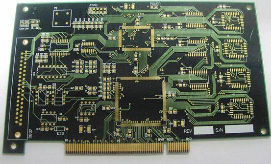
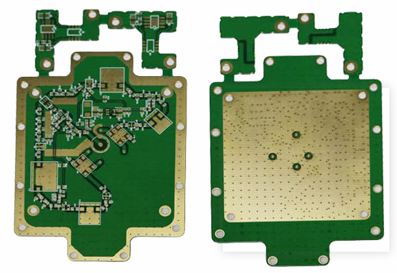
The PCB copper foil substrate provides a support for the installation and interconnection of electronic components. With the trend of light and thin electronic systems, high functionality, high density, and high reliability, the quality of the PCB copper foil substrate will directly affect the trust of electronic products Spend.
In the manufacture of PCB copper foil substrates, there are a lot of attention to the quality control of thickness. Generally speaking, there are quality control of film semi-finished products and the matching of pressing conditions, so the thickness result is the comprehensive result of all process control.

In the past, PCB manufacturers only required the thickness of the substrate to reach the level of IPC-4101[1] CLASS B, but since 2000, they have required CLASS C or higher requirements to meet the market trend of high-level and high-density printed circuit boards. These requirements PCB industry still feel that it is not enough, and began to quote Statistical Process Control (SPC, Statistical Process Control) [2], the most commonly used are process accuracy (Ca, Capability of accuracy, closer to 0, the better) and process capability Index (Cpk, the higher the number, the better). The calculation formula is:
Ca = (measured average value-specification center value)/half of specification tolerance * 100%
Cpk = Min (upper specification limit-average value, average value-lower specification limit) / 3 standard deviations
The citation of statistical process control not only requires products to be within the specification limits, but also requires concentration on the central value of the specifications. However, this method is mainly used for in-plant process improvement. If the Cpk is blindly required to reach a high level, regardless of the upper and lower limits of the specifications., May make a joke, or re-select all products, increasing costs. For example, 6mil 1/1 PCB copper foil substrate, assuming that the copper thickness is 8.5mil as the median value and the thickness distribution curve belongs to the normal distribution, the measured average value is 8.5 (Ca=0), the thickness distribution is 8.08~8.92, Class C The upper and lower limits of the specification, Cpk can reach 1.67, but the Class D specification drops to 1.33.
Therefore, Cpk and specifications need to be negotiated by suppliers and manufacturers together.
Cpk is calculated from a whole batch of data. If the Cpk is unqualified, the whole batch is returned in theory. Intuitively, it feels unreasonable, because how can we return products that meet specifications? Therefore, it can be understood that even if all qualified products can be produced in the process, the Cpk may be unqualified because some processes are unstable or the average value is not in the central value of the specification, indicating that there is still room for improvement in the process. In order for the Cpk to be qualified, a screening test can be taken to remove products close to the upper and lower limits of the specification to obtain a higher Cpk later, but it will reduce the yield. In factories that formulate bonuses for the yield, it may cause on-site staff to rebound.
2. Method
In the early days, the edge of the board was measured manually with a micrometer, but there were traces that were difficult to inspect completely. Therefore, a laser thickness gauge made of a non-contact laser displacement sensor was used.
The classification should be in accordance with IPC regulations. The classification method can be a labeling machine. Class A uses a red label and Class B uses a blue label. If the customer has more stringent requirements, it can be sub-station processing. It is divided into four levels and four stacks. plate.
3. Architecture
The thickness gauge developed by the laser displacement sensor is optical-electromechanical integration. The optical design part has been designed as an independent component of the laser displacement sensor. Therefore, only the electromechanical integration is required, and the software expansion function is required. Figure 3 shows the architecture flow of the thickness gauge.
The selection of various components and the connection of each component are extremely important, otherwise errors and instability will inevitably follow.
3.1 Displacement sensor
The selection of the displacement sensor must consider the characteristics of the PCB copper foil substrate and the allowable tolerance resolution. The measurement distance, resolution, linearity and sampling period can usually be compared. The measurement distance needs to include the thickness of all PCB copper foil substrates to be tested; the resolution needs to match the sensor catalog and remarks. The same resolution has a smaller number of samples, which means better; the smaller the linearity, the better, for example, the measurement distance is +/ -5mm, linearity is 1% FS & 0.1% FS, the maximum error is 0.1mm & 0.01mm (5mm*2*0.1%) respectively; if the sampling period is slow, the fluctuation will be smaller.
3.2 Analog-to-digital conversion card
The choice of analog-digital conversion card (ADC card) focuses on resolution. In the current thin-plate market, 16bit must be used. The allowable tolerance of 12-bit is not enough for thin-plate.
Next, we need to consider the input channel and input voltage range. Generally, the industry design mostly uses three profiles, which requires six displacement sensors, that is, six input channels. Most analog-to-digital conversion cards have up to 16 channels; the output signals of the displacement sensors are: One is voltage, the other is current. The general ranges are -5V ~ +5V & 4 ~ 20 mA respectively. The current can be converted to voltage (within +/-10V) with appropriate resistance for input to analog-to-digital conversion card.
3.3 Digital card
Numbers are 0 and 1. Digital I/O card only has low potential and high potential. Basically, 0V represents low potential, which is 0, and 5V represents high potential, which is 1. Digital signal input (DI) includes counters, Photoelectric switches, etc., can be used to notify the PCB copper foil substrate to pass and display the peripheral conditions of the instrument. The digital signal output (DO) is used for control or alarm. The control includes the display of quality analysis results. The performance method may be the computer screen display OK/NG, alarm Or hierarchical (connected back to the program logic controller, PLC).
The analog-digital conversion card and the digital card have been combined into one, which is called a multifunction card (Multifunction I/O card). Unless there are too many digital signals, one card is enough.
4. Theory
After the thickness test is carried out for a period of time, the thickness measurement equipment may be subject to aging, damage or customer demand, and must be maintained and improved continuously. At this time, it is necessary to start from theory to judge the cause of abnormality.
5 Conclusion
The entire PCB copper foil substrate laser thickness measurement system, including laser displacement sensor (light), mechanism design (machine), circuit, photoelectric switch, wiring (electricity) and software are integrated together. Each PCB component is related to the whole The system is good or bad. If you don’t understand the architecture process, once the fault cannot be dealt with in real time, the on-site personnel will not trust, the entire system becomes a burden, and there is no quality control. Therefore, you must use this equipment with caution and fear.