PCB component dynamic analysis PCB proofing
For avionics, failures caused by vibration and shock will greatly reduce its reliability and bring extremely serious consequences. PCB also often appears in real-time vibration testing of avionics. Through the dynamic analysis and design of PCB components, the possibility of environmental test failure can be effectively reduced, and the reliability and quality of avionics can be improved.
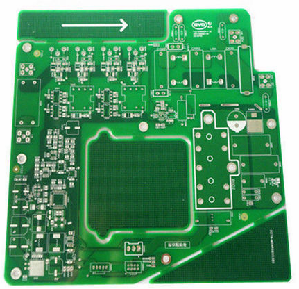
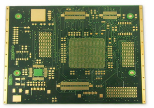
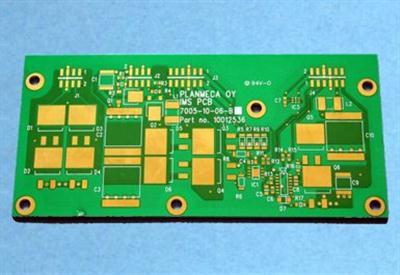
Dynamic analysis is based on dynamic characteristic analysis. The dynamic model of PCB assembly can be established through dynamic characteristic analysis. Only by establishing an accurate kinetic model can the kinetic analysis be carried out effectively. To this end, this article attempts to use the pre-test analysis techniques of finite element analysis (FEA) and experimental modal analysis (EMA) to analyze the dynamic characteristics of the PCB components of avionics (as shown in Figure 1), and establish the limited PCB components Metadynamic analysis model.

1. Limited deterioration analysis
As a mature numerical analysis technology, finite element analysis (FEA) is widely used in the statistical analysis of the dynamic characteristics of PCB components in electronic equipment. In addition, FEA can help engineers design more reliable PCB components to predict potential failures and fatigue at the beginning of the design. This article takes the PCB assembly of avionics (Figure 1) as the research object. Its dimensions (length x width x thickness) are 133.5mm x 79mm x 1.8mm, which are fixed on the four corners of the PCB on the housing of the electronic device by screws. The external dimensions and fixing methods of the PCB components are similar to the required standard test PCBs in terms of size and fixing methods, but their thickness is slightly thicker. Components and plug-ins are assembled with PCB through surface mount technology (SMT), and the components are mainly packaged in BGA, QFP and SOP.
2. Finite element analysis model
Material physical performance parameters of each part of PCB assembly. Based on the geometric information of PCB components and related material information, a finite element analysis model was established in ANSYS. . Because the result is the dynamic performance data displayed by the PCB assembly as a whole, rather than the detailed data of the assembly itself, the components and plug-ins are simplified when building the model. Specifically, rectangular and square blocks are used to simulate components, and their approximate shapes are used to simulate plug-ins. Each part of the finite element analysis model uses three-dimensional solid elements (SOLID187) for meshing (using solid elements for mesh intrusion). Although the amount of calculation has increased, the workload of the model from CAD to CAE is greatly reduced. Conducive to the promotion of engineering applications), and the use of multi-point constraints (MPC) to simulate the connection between the plug-in and the PCB. At the same time, since the rigidity of the electronic housing is much greater than that of the PCB assembly, fixed support constraints are imposed on the screw holes at the four corners in the finite element model to simulate the screw connection of the PCB assembly and the housing to the device housing.
3. Results of finite metamorphosis analysis
The finite element model of the target PCB component is established, and the Block Lanczos method is used for modal analysis. Modal analysis is to solve the characteristic equation of the system. The characteristic equation of a general multi-degree-of-freedom system can be used to obtain the characteristic value and characteristic vector of the PCB system, which is the natural frequency and vibration mode of the vibration system.
In the finite element modal analysis, the mass matrix of the PCB system is assembled from the unit mass matrix. The stiffness matrix of the system is composed of the unit stiffness matrix in the analysis of finite metamorphism.
Through modal analysis, the first and third natural frequencies and vibration types of the target PCB assembly fixed with four screws are obtained. The first-order vibration type of PCB components is first-order bending, and the second-order is second-order bending. The first-order vibration type is torsion, and the third-order vibration type is sinusoidal wave bending. These vibration patterns are similar to four screws fixed on a JEDEC standard board.