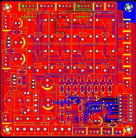
1. In a system where both digital and analog coexist, there are two processing methods. One is to separate the digital ground from the analog ground. For example, in the stratum, the digital ground is an independent piece, the analog ground is an independent piece, and a copper sheet or FB magnet is used for a single point. Bead connection, but the power supply is not separated; the other is that the PCB analog power supply and the digital power supply are separated by FB connection, and the ground is the unified ground. Are the two PCB methods the same effect?
It should be said that it is the same in principle. Because power and ground are equivalent to high-frequency signals.
The purpose of distinguishing analog and digital parts is to resist interference, mainly the interference of digital circuits to analog circuits. However, segmentation may cause incomplete signal return paths, affect the signal quality of digital signals, and affect the EMC quality of the system. Therefore, no matter which plane is divided, it depends on whether this is done, whether the signal return path is enlarged, and how much the return signal interferes with the normal working signal. There are also some mixed designs, regardless of power supply and ground. In the layout, the digital part and the analog part are placed and routed separately to avoid cross-zone signals.
2. Safety issues: What is the specific meaning of FCC and EMC?
FCC: federal communication commission
EMC: electro megnetic compatibility

FCC is a standards organization, EMC is a standard. The promulgation of standards has corresponding reasons, standards and test methods.
3. What is PCB differential wiring?
Differential signals, some of which are also called differential signals, use two exactly the same signals with opposite polarities to transmit one data, and the decision depends on the level difference of the two signals. In order to ensure that the two signals are exactly the same, they must be kept parallel when wiring, and the line width and line spacing remain unchanged.
4. What are the PCB simulation software?
There are many types of simulations. For high-speed digital circuit signal integrity analysis, simulation analysis (SI) commonly used software includes icx, signalvision, hyperlynx, XTK, speectraquest and so on. 5. How does PCB simulation software perform LAYOUT simulation?
In high-speed digital circuits, in order to improve signal quality and reduce wiring difficulty, multi-layer boards are generally used to allocate special power layers and ground layers.
6. How to deal with the layout and wiring to ensure the stability of signals above 50M
The key to high-speed digital signal wiring is to reduce the impact of transmission lines on signal quality. Therefore, the layout of high-speed signals above 100M requires the signal traces to be as short as possible. In digital circuits, high-speed signals are defined by signal rise delay time. Moreover, for different types of signals (such as TTL, GTL, LVTTL), the methods to ensure signal quality are different.
7. The radio frequency part, the intermediate frequency part, and even the low frequency circuit part that monitors the outdoor unit are often deployed on the same PCB. What are the requirements for the material of such a PCB? How to prevent the radio frequency, intermediate frequency and even low frequency circuits from interacting with each other Interference between?
Hybrid circuit design is a big problem. It is difficult to have a perfect solution.
Generally, the radio frequency circuit is arranged and wired as an independent single board in the system, and there is even a special shielded cavity. Moreover, the radio frequency circuit is generally single-sided or double-sided, and the circuit is relatively simple, all of which are used to reduce the influence on the distribution parameters of the radio frequency circuit and improve the consistency of the radio frequency system. Compared with general FR4 materials, RF circuit boards tend to use high-Q substrates. This material has a relatively small dielectric constant, small transmission line distributed capacitance, high impedance, and small signal transmission delay. In hybrid circuit design, although the radio frequency and digital circuits are built on the same PCB, they are generally divided into radio frequency circuit areas and digital circuit areas, and they are laid out and routed separately. Use grounding via tape and shielding box to shield between them.
8. For the radio frequency part, the intermediate frequency part and the low frequency circuit part are deployed on the same PCB, what solution does mentor have?
Mentor's board-level system design software, in addition to basic circuit design functions, also has specialized RF design modules. In the RF schematic design module, provide parameterized device models, and provide bidirectional interfaces with EESOFT and other radio frequency circuit analysis simulation tools; in the RF LAYOUT module, provide pattern editing functions specifically for radio frequency circuit layout, and The bidirectional interface of EESOFT and other radio frequency circuit analysis simulation tools can back-annotate the schematic diagram and PCB board for the analysis and simulation results. At the same time, using the design management function of Mentor software, design reuse, design derivation, and collaborative design can be easily realized. Greatly accelerate the process of hybrid circuit design.