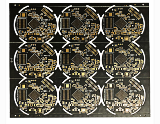
High-frequency boards are used more and more under the demand of high-frequency and high-speed fields, especially the Rogers series of high-frequency boards (microwave radio frequency boards) are very popular. High-frequency boards need a lot of skills in manufacturing, otherwise it will affect Correlation between various equipment.
High-frequency circuit board/high-speed PCB manufacturing layout skills
1. The lead bends between the pins of high-speed electronic equipment as little as possible
The lead wire of high-frequency circuit wiring is best to use all straight lines, which need to be transferred. It can be used for 45-degree broken lines or circular arcs. This requirement is only used to improve the fixing strength of copper foil in low-frequency circuits, while in high-frequency circuits, satisfying this requirement can reduce the external emission and inter-examination of high-frequency signals. coupling.
2. The shorter the lead between the pins of high-frequency circuit equipment, the better
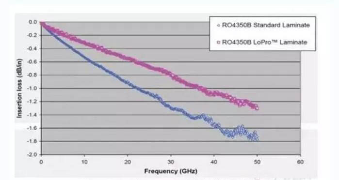
The radiation intensity of the signal is proportional to the trace length of the signal line. The longer the signal lead of the high-frequency board (microwave radio frequency board), the easier it is to couple to the components close to it. High-frequency signal lines such as crystal oscillator, DDR data line, LVDS line, LISB line, HDMI line, etc. are required to be as short as possible.

3. Add high-frequency decoupling capacitors to the power pins of the integrated circuit block
Add a high-frequency decoupling capacitor to the power supply pin of each integrated circuit block. Add high-frequency decoupling capacitors for the power supply pins. It can effectively suppress the interference caused by high-frequency harmonics on the power supply pins.
4, pay attention to the "crosstalk" introduced by the signal lines in close parallel routing
High-frequency circuit wiring should pay attention to the "crosstalk" introduced by the close parallel routing of signal lines. Crosstalk refers to the coupling phenomenon between signal lines that are not directly connected. Because high-frequency signals are transmitted in the form of electromagnetic waves along the transmission line, the signal line will act as an antenna. The energy of the electromagnetic field will be emitted around the transmission line. Undesirable noise signals are generated due to the mutual coupling of electromagnetic fields between the signals. Called crosstalk (Crosstalk). The parameters of the PCB layer, the spacing of the signal lines, the electrical characteristics of the driving end and the receiving end, and the signal line termination method have a certain influence on the crosstalk.
5, the less the lead layer replacement between the pins of high-frequency circuit equipment, the better
The so-called "the less interlayer replacement of leads, the better" means that the fewer vias (Via) used in the process of component connection, the better. It is measured that one via can bring about 0.5pF of distributed capacitance, and reducing the number of vias can significantly increase the speed and reduce the possibility of data errors.
6.Multilayer circuit board(high frequency board) wiring
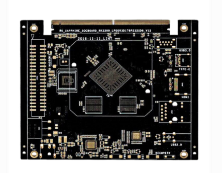
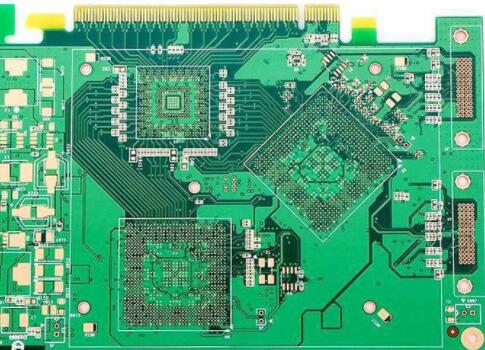
High-frequency circuit s tend to have high integration and high wiring density. The use of multi-layer circuit boards (high-frequency boards) is not only necessary for wiring, but also an effective means to reduce interference. In the PCBLAYOUT stage, a reasonable choice of a high-frequency board (microwave radio frequency board) with a certain number of layers can greatly reduce the size of the printed circuit board, make full use of the intermediate layer to set up the shield, better complete the nearest grounding, and effectively reduce the parasitic inductance Together with shortening the signal transmission length, it can also greatly reduce the cross-interference between signals. All these methods are beneficial to the reliability of high-frequency circuits. According to data, when the same kind of data is used, the noise of the four-layer circuit board is 20dB lower than that of the double-sided circuit board. However, there is also a problem at the same time. The higher the number of PCB circuit boards, the more messy the manufacturing process, and the higher the unit cost. This requires us to select PCB circuit boards with appropriate layers in addition to selecting the appropriate number of layers. Reasonable layout planning of meta-equipment and selection of correct wiring rules to complete the planning.
7, the ground wire of the high-frequency digital signal and the ground wire of the analog signal are used as a barrier
When imitating the ground wire, digital ground wire, etc., connect to the public ground wire, use high-frequency choke magnetic beads to connect or directly block and select the appropriate local single-point interconnection. The ground potential of the high-frequency digital signal ground wire and the ground potential of the imitating ground wire are generally inconsistent. There is often a certain voltage difference between the two. Moreover, the ground wire of the high-frequency digital signal often contains very rich high-frequency signals. When directly connecting the digital signal ground wire and the analog signal ground wire, the harmonic components of the high-frequency signal will disturb the analog signal through the method of ground wire coupling. Therefore, under normal circumstances, the ground wire of the high-frequency digital signal and the ground wire of the imitating signal are to be blocked, and the method of single-point interconnection at an appropriate position can be selected, or the method of interconnection by high-frequency choke magnetic beads can be selected.
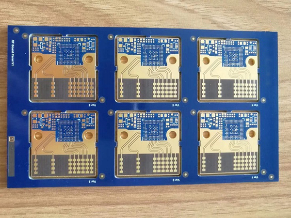
High-frequency board(microwave radio frequency board) between the effects of equipment
If the high-frequency board (microwave radio frequency board) is not planned in place, it will cause the line disorder between periods, directly affect the transmission speed, and even cause the high-frequency board (microwave radio frequency board) to fail the test. Therefore, it is necessary to pay attention to typesetting skills in the manufacture of high-frequency boards (microwave radio frequency boards). For more high-frequency boards (microwave radio frequency boards), please consult Shenzhen ipcb.