Reliability test of PCBA lead-free solder joints
PCBA lead-free solder joint reliability test is mainly to conduct thermal load test (temperature shock or temperature cycle test) on electronic assembly products; perform mechanical stress test on electronic device joints according to fatigue life test conditions; use models for life evaluation. PCBA lead-free solder joint reliability test methods mainly include visual inspection, X-ray inspection, metallographic section analysis, strength (tensile, shear), fatigue life, high temperature and high humidity, drop test, random vibration, and reliability testing methods Wait. A few of them are introduced below:
1. Visual inspection
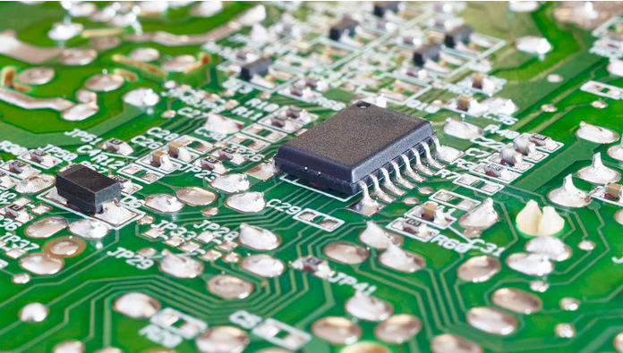
Lead-free and lead-free PCBA solder joints are different from the outside, and will affect the correctness of the AOI system. The stripes of PCBA lead-free solder joints are more obvious and rougher than the corresponding leaded solder joints, which are caused by the phase change from liquid to solid. Therefore, this type of solder joint looks rougher and uneven. In addition, due to the high surface tension of lead-free solder in PCBA processing, it is not as easy to flow as lead solder, and the rounded corners formed are not the same.
2. X-ray inspection
In the spherical solder joints of PCBA lead-free soldering, the number of virtual soldering increases. PCBA lead-free solder has a higher soldering density, which can detect cracks and virtual soldering during soldering.

Copper, tin, and silver should be classified as "high-density" materials. In order to characterize the characteristics of excellent soldering, monitor PCBA assembly processes, and perform the most important structural integrity analysis of PCBA solder joints, it is necessary to recalibrate the X-ray system. The testing equipment has higher requirements.
3. Metallographic section analysis
Metallographic analysis is one of the important methods of experimental research on metal materials. In PCBA solder joint reliability analysis, the metallographic structure of the solder joint profile is often taken for observation and analysis, so it is called metallographic section analysis. Metallographic section analysis is a destructive inspection. It has a long sample production cycle and high cost. It is often used for analysis after solder joint failures, but it has the advantages of being intuitive and speaking with facts.
4. Automatic solder joint reliability detection technology
Automatic solder joint reliability detection technology is an advanced technology that uses photothermal method to detect the quality of circuit board solder joints point by point. It has the characteristics of high detection accuracy, good reliability, and no need to touch or damage the tested solder joints during testing. During the inspection, certain laser energy is injected into the solder joints of the PCBA board point by point, and at the same time, infrared detectors are used to monitor the thermal radiation generated by the solder joints after being irradiated by the laser. Since the heat radiation characteristics are related to the quality of the solder joints, the quality of the solder joints can be judged accordingly.
5. Perform temperature-related fatigue tests
In the PCBA lead-free process solder joint reliability test, the more important thing is the temperature-dependent fatigue test for the different thermal expansion coefficients of the solder joint and the connected components, including isothermal mechanical fatigue test and thermal fatigue test.
The most important point when evaluating the reliability of PCBA lead-free solder joints is to select the most relevant test method, and to clearly determine the test parameters for a specific method. In the PCBA lead-free process solder joint reliability test, it is more important to conduct temperature-dependent fatigue testing for the different thermal expansion coefficients of solder joints and connected components, including isothermal mechanical fatigue testing, thermal fatigue testing, and corrosion resistance testing. According to the test results, it can be confirmed that different lead-free materials have different resistance to mechanical stress at the same temperature. At the same time, studies have shown that different lead-free materials show different failure mechanisms and failure modes.
Commonly used testing equipment and functions in SMT patch processing
The process flow of SMT patch processing is complicated and cumbersome, and problems may occur in every link. In order to ensure that the product quality is qualified, it is necessary to use various testing equipment to detect faults and defects and solve the problems in time. So what are the common testing equipment in SMT patch processing? What is its function?
1. MVI (manual visual inspection)
2. AOI testing equipment
(1) Where the AOI inspection equipment is used: AOI can be used in multiple locations on the production line, and each location can detect special defects, but the AOI inspection equipment should be placed in a position that can identify and correct the most defects as soon as possible.
(2) Defects that AOI can detect: AOI is generally inspected after the PCB board etching process, mainly to find the missing and redundant parts on it.
3. X-RAY detector
(1) Where the X-RAY detector is used: it can detect all solder joints on the circuit board, including solder joints that are invisible to the naked eye, such as BGA.
(2) Defects that can be detected by the X-RAY detector: The defects that can be detected by the X-RAY detector are mainly defects such as bridges after welding, cavities, excessive solder joints, and too small solder joints.
4. ICT testing equipment
(1) Where ICT is used: ICT is geared towards production process control and can measure resistance, capacitance, inductance, and integrated circuits. It is particularly effective for detecting open circuit, short circuit, component damage, etc., with accurate fault location and convenient maintenance.
(2) Defects that ICT can detect: it can test the problems of virtual welding, open circuit, short circuit, component failure, and wrong material after welding.
In addition to the use of these testing equipment, the quality assurance of SMT chip processing is also inseparable from the strict quality management monitoring of the chip processing manufacturer.