An external adapter was added during the test of a certain vehicle recorder. When the machine was powered on and tested, it was found that the radiation exceeded the standard, with the specific frequency points being 84MHZ, 144MH and 168MHZ. It is necessary to analyze the causes of the radiation exceeded and give corresponding countermeasures. Radiation test data are as follows:

1. Radiation source analysis:
The product consists of a single PCB board with a 12MHZ crystal on it. The exceeding frequency points happen to be the double frequency of 12MHZ, and the analysis of the screen and camera of the machine prone to exceeding EMI radiation shows that lC-CLK is 33MHZ, while the camera MCLK is 24MHZ. Through elimination, it was found that the superstandard points still existed after removing the camera, while the superstandard points were reduced by shielding the 12MZH crystal. Therefore, it was determined that the 144MHZ superstandard points were related to the crystal.

2. Principle of radiation generation
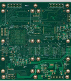
As can be seen from the PCB layout, the 12MHZ crystal is just placed at the edge of the PCB. When the product is placed in the test environment with radiation emission, the high-speed device of the tested product will form a certain capacitive coupling with the reference grounding in the laboratory, resulting in parasitic capacitance and common mode radiation. The larger the parasitic capacitance is, the stronger the common mode radiation is. The parasitic capacitance is essentially the electric field distribution between the crystal and the reference ground. When the voltage between the two is constant, the more the electric field distribution between the two, the greater the electric field intensity between the two, and the larger the parasitic capacitance will be. The electric field distribution between the crystal at the edge of PCB and in the middle of PCB.
As can be seen from the figure, when the crystal oscillator is arranged in the middle of PCB or far from the edge of PUB, most electric field is controlled between the crystal oscillator and the working ground due to the existence of the working ground plane (GND) in PCB, that is, the electric field distributed to the reference grounding floor is greatly reduced in PCB, resulting in a decrease in radiation emission.
3. Handling measures
Move the crystal oscillator inward to make it at least 1cm away from the edge of PCB, and apply copper in the range of 1cm away from the crystal oscillator on the surface of PCB, and connect the copper on the surface with the PCB floor plane through the hole. The spectrum diagram of the modified test results is shown below, from which it can be seen that the radiation emission has been significantly improved.
4. Thinking and enlightenment
Capacitive coupling between high-speed printed lines or devices and the reference ground plate can cause EMI problems, and placement of sensitive printed lines or devices at the edges of the PCB can cause interference problems.
If the design must be arranged at the edge of the PCB for some other reasons, then you can cloth a working ground wire on the edge of the printed line, and increase the hole to connect the working ground wire with the working ground plane.