After getting the faulty PCB, what to do first, and what to do later, must be sequenced and the steps must be clear. Don't rush to do it, dismantle it in a mess, fail to repair it, and cause the breakdown to expand. Doing more useless work in vain is a waste of time and energy.
First of all, you should learn as much as possible about the fault phenomenon reported by PCB users, and ask more about the situation when the fault occurred, and it is best to learn about the fault from the on-site "witness". Understand whether the fault occurs suddenly or gradually; whether it will occur under certain circumstances; and what alarms are there when the fault occurs. Only in this way can we be targeted and find faults in a targeted manner. Users are in different roles. Sometimes the phenomena they see are only appearances, and even fault descriptions differ greatly from actual ones. As maintenance technicians, they should be good at identifying useful and useless information.
Next is the "kanban", that is, visually inspect the circuit board for faults. Don't use "kanban" improper technology. A lot of maintenance practice tells us: Many circuit board failures can be seen! The fault seen is simple, direct and obvious, and comparing it with the reflected fault phenomenon can explain the problem. Maintenance is also like treating a disease. It also pays attention to "watching, smelling, and asking", and "kanban" should be regarded as inspection.

"Kanban", what to look at?
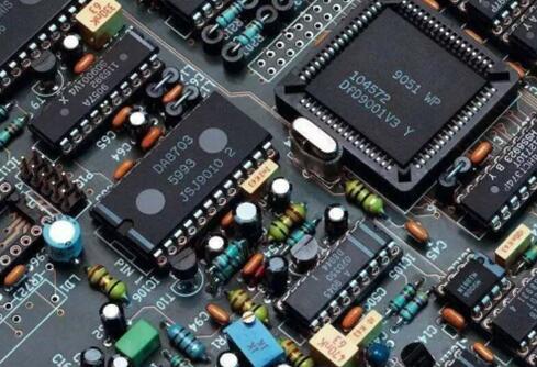
1: See if there are any traces of damage to the PCB components and lines. Whether the insurance is blown, whether the components on the board are obviously burnt, scorched, whether the component pins are rusted, whether the connectors are poorly contacted, whether the capacitors, batteries and other components are leaking, whether the circuit copper foil is traced Corrosion damage, whether the components and circuits are mechanically damaged, and whether the SMD pins are open. In order to see clearly, light and magnifying glass can be used together to avoid the slightest possibility of malfunction. The damage probability of various components is different, such as aluminum electrolytic capacitors. After a long time, they will surely age and cause problems. Under various environments, the damage probability of each part of the board is also different. problem. When kanban, these situations also need to be considered and focused.
2: Whether the kanban has been repaired by others. Many boards that are repaired are not first-hand. After the hands of others, if the skills of others are acceptable, it means that many failure possibilities have been eliminated, and it will be difficult to repair again. You must be prepared to chew hard bones. If others lack maintenance experience, not only the initial failure exists after the maintenance, but also new failures may be added. Or it is possible that others have found the fault point, but the handling method is improper, such as poor welding or poor connection, resulting in a bad test machine. Pay attention to the maintenance traces of others when you sign the board, and eliminate the artificial secondary faults such as reverse soldering, wrong soldering, and false soldering of components.
3: The old and new years of the kanban. Most of the ICs on the board will mark the production date. For example, 9622 means the product produced in the 22nd week of 1996. Most of the ICs required for the assembly of the brand company’s equipment are ordered directly from the IC manufacturer, so the equipment delivery date will be slightly behind the IC marked Date, so by looking at the date marked on the IC, you can probably know the date of use of the device, so that we can estimate the approximate type of failure. If the circuit board has been used for more than seven or eight years, the components are likely to fail due to aging and damage. If the board is used within three or four years, the board failure should be due to the poor working environment, improper operation by personnel, or purely random factors.
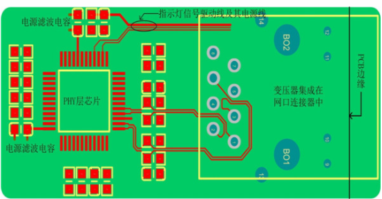
"Kanban" can't stop at simply "watching" either. While watching, we must also think about it. It should be noted that most of the circuit boards we are facing do not have drawings. Experienced repairers must "have a clear picture". Seeing the outline of the board, you will know its principle and structure, and the component combination of this board will also be in your mind. Quickly and clearly, the maintenance plan has taken shape. For example, if you are repairing a switching power supply, there must be a PWM chip, a switching tube, and a switching transformer; if you are repairing a single-chip circuit, there must be information such as crystal oscillator, reset, power supply, and program location; if you are repairing an analog circuit, there must be some The resistors and capacitors are matched around the op amp chip.
From seeing the real object on the board to forming a drawing in the mind, it provides a guide for the subsequent troubleshooting. After no obvious faults are found, necessary equipment, such as multimeters, oscilloscopes, and online testers, should be used to detect the power-on and non-power-on conditions of the circuit board. When not energized, use the continuity test block, diode test block, and resistance test block of the multimeter to test the component, and use the online tester to test the component VI curve. According to the fault phenomenon reported by the user, it is necessary to focus on the detection. It is best to click the acupuncture point from the beginning. Some components cannot be determined as good or bad without being disassembled from the board, so they must be tested after disassembly. But there is a principle, try to test the components on the board as much as possible. If it is not a last resort, do not disassemble it, because disassembly takes time and may cause secondary failures, especially those with dense pins, which are easy to remove., Welding can be relatively difficult.
The power supply is the root cause of many failures. To ensure the normal operation of the circuit board, the power supply part of the PCB must be ensured to be normal. The power supply is normal, including parameters such as voltage size, drive capability, and ripple coefficient. Power-on detection is the most intuitive method. It is necessary to prepare a transformer with a power of 250W, which can isolate and transform 220V AC voltage into common AC voltages such as 12V, 24V, 110V, 380V, etc., in order to cope with the power consumption of different equipment. To prepare a three-channel output adjustable DC maintenance power supply, the maximum output current is above 3A, you can directly apply voltage to the DC power supply part of the board to simulate the working condition of the circuit board. After the equipment or circuit board is powered on, some faults can be visually displayed, but some faults cannot be observed, because the load and peripheral circuits need to be connected. When conditions permit, we can simulate the periphery and load as much as possible. After the device or board is powered on, pay attention to the status of various indicators and various alarm messages, and compare the relevant manual documents that can be found to narrow the scope of fault finding.
Many PCB failures have a joint damage relationship, and more than one PCB component may be damaged. For example, a component is damaged due to a short circuit, and other components connected in series with this component also pass a large current and may be damaged. If the component is damaged due to excessive voltage, other components connected in parallel with this component are also subject to excessive voltage and may be damaged. For these situations, a thorough investigation should be conducted.
You must also be cautious in the finishing work after maintenance. Components with orientation during assembly and welding should refer to the screen printing on the board or the marks made during disassembly to prevent welding errors, reverse welding, and false welding. When power-on inspection, confirm the magnitude and positive and negative direction of the applied voltage, so as to avoid losing money to the final repair.