Generally speaking, in addition to the normal assembly and test process, the electronic finished fr4 pcb product assembly plant will more or less establish several control checkpoints for testing and inspection to ensure the quality of the products it produces on its production line. The following two checkpoints are most commonly seen, which are set at the intermediate stations of product assembly and electrical testing.

Tapping test
The main purpose of knocking is to check whether the finished product has any bad assembly, including scraping the empty, false solder, solder ball, solder bead of electronic parts, and whether the mechanism and screw are assembled in place. The knocking test rod is usually made by inserting a wooden rod with a elastic ball. When knocking, hold one end of the wooden rod and use the elastic ball to knock the finished product. It is better to turn on the power when knocking. For products with pictures, pay attention to whether there are abnormalities in the pictures, because some electronic parts with poor welding may only have open circuit or short circuit problems when knocking. Usually, the knock test will be placed at the first step of the electrical test, because we do not know whether the product problem has been knocked out after the knock. If there is no electrical test after the knock, it is likely that the defective products will flow out to the customers. The striking position is very important, because the striking effect of different positions is different. It is necessary to knock at the place where resonance can occur in the solid of the product, and the general test needs to knock three times in succession. It is best to find the most vulnerable part of the product design to knock. If you only knock in the hollow place, it will not be effective. In addition, the size and weight of the elastic ball will affect the effect of knocking, so we should pay attention to it.
Drop test
The drop test here refers to the quality verification of products before shipment, not the drop test of DQ (Design Quality). The drop test is subject to the bare damage of the product. The purpose is the same as the above knock test. When checking whether the finished product has any bad assembly, this test and the knock test can complement each other. The knock test focuses on (resonance) and knocks three times in succession; If it falls, it will only be done once. The fallen table top is made of solid wood, and a layer of 3~5mm electrostatic table mat is paved on it. During the drop test, it is free to fall without power supply or power on. Like the knock test, the electrical test must be carried out after the drop test to ensure that the product functions well and has no appearance damage. The height of fall usually ranges from 76.2 mm (3 inch) to 300 mm, which is generally distinguished by the weight of the product. The heavier the weight, the lower the height of fall. The following table is only a rough idea and for reference only. Everything should be subject to the actual products of each company.
Personal experience shows that operators of production line are not afraid to drop products, so the drop test will fall lower and lower. In fact, operators should know that the purpose of drop test is to pick out the defective products. Rather than letting the defective products flow out to the customer's hands and be returned later, it is better to drop them first in production line, and the products should be rewarded if they fall to death. In addition, when R&D is doing product research and development, many machines will fall to more than 76Cm and not die, and still fall on the concrete floor with six sides and four (8) corners, so it is not necessary to be afraid that the product will be damaged if it falls down, but the appearance will be damaged if it accidentally falls down.
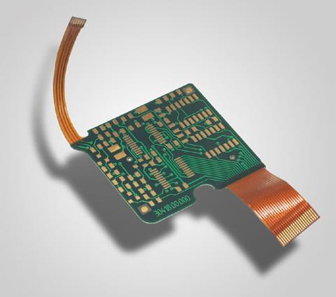
Recently, it has been found that some flexible circuit boards (FPCs) have bad feedback of line breaks. In order to be lighter and thinner, we abandoned 1/2 ounce (oz) and began to use 1/3 ounce copper foil a few years ago. However, the thinner the copper foil, the weaker its ability to withstand bending, that is, rolled copper. In fact, when these defective products were sent back, the open circuit was measured with a three-way ammeter, but at the beginning, it was impossible to find out where the broken soft board of these lines broke. Finally, the supplier was fierce. They bent the FPC bit by bit, not dead, but forced the FPC to bend, and then checked under the microscope, and finally found the break of the copper foil line. That is to say, although these lines have been broken, they can't be seen with a microscope even when lying flat. Since the copper foil lines were found broken, and the broken parts of the copper foil lines were not dead breaks in our use process, and there was no sign of bending during the assembly process, so it was obvious that there was a problem when FPC came in, and it only emerged after a period of use.
Send the defective FPC back to the original FPC factory for analysis. The other party should also be very careful. Because we told the other party that all the defective products in the market should be absorbed by the other party, the supplier was very nervous and actively looked for the FPC factory to find the possible cause. After several weeks of efforts, the other party replied that the real reason for FPC fracture was the gap between the copper foil line and the PI layer, so that the copper foil did not have enough support, which caused the fracture after several stress. This argument should be tenable, but the gap should be difficult to avoid, and the rolled copper should have enough ductility to withstand such gap. At present, I personally accept this conclusion, but I doubt it. Because if the wrong copper plating is used, it will be a problem of batch production, rather than such sporadic cases, so it should be some separate reason that causes the FPC line to break, but the gap cannot be avoided on fr4 pcb.