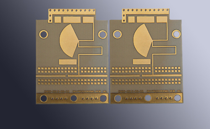
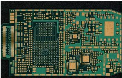
With the development of wireless communication and broadband network, PCB is no longer simply laying metal wires on some insulating substrates to realize the interconnection of circuits. In many cases, RF PCB substrates and metal conductors have become part of functional components. Especially in RF applications, components interact with PCB substrate, so PCB design and PCB manufacturing increasingly have a critical impact on product functions. As shown in the figure below, the conductors on a typical microwave RF PCB are all components.

Our RF PCB manufacturers are also more involved in things related to RF design, especially in high-frequency and high-speed signal transmission. Similarly, PCB designers must have a deep understanding of PCB manufacturing process in order to comprehensively produce qualified and high-performance PCBs.
1. Dielectric constant (DK)
Dielectric constant (Dk, ε, Er) determines the speed of electrical signal propagation in the medium. The speed of electrical signal propagation is inversely proportional to the square root of the dielectric constant. The lower the dielectric constant, the faster the signal transmission. Let's make a visual analogy, just like you are running on the beach. The water depth submerges your ankles. The viscosity of water is the dielectric constant. The more viscous the water is, the higher the dielectric constant is, and the slower you run.
The dielectric constant is not very easy to measure or define. It is not only related to the characteristics of the medium itself, but also related to the test method, test frequency, and the state of the material before and during the test. The dielectric constant will also change with the change of temperature. Some special materials have been developed with consideration of temperature Humidity is also an important factor affecting the dielectric constant, because the dielectric constant of water is 70. A little water will cause significant changes
The following are the dielectric constants of some typical materials (at 1Mhz):
Vacuum 1.0
Pure PTFE 2.1
GYPTFE2.2-2.3
GX-PTFE2.55
Cyanate ester/glass 3.2
Cyanate ester/quartz 2.8-3.4
Polyimide quartz 3.5-3.8
Polyimide glass 4.0-4.6
Epoxy resin glass (FR4) 4.4-5.2
Nonwoven aromatic amine (aramid) 3.8-4.1
Aromatic amine (woven fabric) 3.8-4.1
Ceramic-filled PTFE 6.0-10.2
Foamclad (Arlon patent) 1.15-1.3
Water 70.0
For high-speed and high-frequency applications, the ideal material is the air medium wrapped with copper foil,
In addition to directly affecting the transmission speed of the signal, the dielectric constant also determines the characteristic impedance to a large extent. In different parts, the characteristic impedance matching is particularly important in microwave communication. If the impedance mismatch occurs, the impedance mismatch is also called VSWR (standing wave ratio)
CTEr: Because the dielectric constant changes with temperature, and the materials used in microwave are often outdoors, even in space environment, CTEr (coefficient of change of dielectric constant with temperature) is also a key parameter. Some PTFE filled with ceramic powder can have very good characteristics, such as CLTE
2. Loss factor (Df)
In addition to the dielectric constant, the loss factor is an important parameter affecting the electrical properties of materials Dielectric loss is also known as loss tangent, loss factor, etc. It refers to the loss of signal in the medium, or energy loss This is because when high frequency signals (they constantly transform between positive and negative phases) pass through the medium layer, molecules in the medium try to orient according to these electromagnetic signals. Although in fact, because these molecules are cross-linked, they cannot really orient. However, changes in frequency cause the scorers to keep moving, generate a lot of heat, and cause energy loss.
However, some materials, such as PTFE, are nonpolar, so they will not be affected by electromagnetic field, and the loss is small. Similarly, the loss factor is also related to frequency and test method. The general rule is that the higher the frequency, the greater the loss The most intuitive example is the consumption of electric energy in transmission. If the circuit design loss is small, the battery life can be significantly increased; When receiving the signal, the antenna will be more sensitive to the loss of materials and the signal will be clearer.
The commonly used FR4 epoxy resin (Dk4.5) has relatively strong polarity. At 1GHz, the loss is about 0.025, while the loss of PTFE substrate (Dk2.17) under this condition is 0.0009. Compared with glass filled polyimide, quartz filled polyimide has low dielectric constant and loss, because the silicon content is pure.
The following figure shows the molecular structure of PTFE. We can see that its structure is very symmetrical, the C-F bond is tightly bound, and there is no polar group. Therefore, the possibility of swaying with the change of electromagnetic field is very small, which is shown in the electrical characteristics of small loss.

3. Coefficient of thermal expansion (CTE)
The coefficient of thermal expansion is usually abbreviated as CTE, which is one of the important thermal mechanical properties of materials. It refers to the expansion of materials when they are heated. The actual material expansion refers to the volume change, but due to the characteristics of the substrate, we often consider the expansion in the plane (X -, Y -) and vertical direction (Z -) respectively. The thermal expansion of the plane can often be controlled by the reinforcement layer materials (such as glass cloth, quartz, Thermomount), The longitudinal expansion is always above the glass transition temperature, which is difficult to control. The planar CTE is crucial for installing high-density packages. If the chip (usually CTE at 6-10ppm/C) is installed on a conventional PCB (CTE18ppm/C, PTFE, which is often filled with ceramic powder, such as CLTE and LCCLTE of Arlon Company, is the most representative application for manufacturing 64 layer multilayer boards for global communication satellites
4. Thermal conductivity
In many microwave fields, there are many high-power applications, and the heat dissipation characteristics of materials can greatly affect the reliability of the entire system. Therefore, the thermal conductivity should also be considered. For some special high reliability and high power consumption applications, metal lining (aluminum or copper base) can also be used. Examples of material types: thermal conductivity W/mkPTFE/glass cloth Diclad, Cuclad0.26PTFE/ceramic powder, Glass cloth CLTE0.5AR10000.65AD350i0.45 ceramic powder filled thermosetting material 25N/FR0.45 thermal conductive material 99N1.2FR-40.24-0.26
5. Manufacturability
We understand that PTFE materials are difficult to process, especially for hole metallization, which requires plasma or sodium naphthalene treatment to improve its activity. Moreover, PTFE is a thermoplastic material, and the processing of multilayer boards requires high temperature. Now, a new low loss thermosetting resin material has been developed for high-frequency circuits, which can process multilayer boards without plasma activation, such as Arlon25N/FR. Currently, it is widely used in LNA, In the design of PA and antenna, moisture absorption is also a factor to be considered. Materials with small moisture absorption should be selected as far as possible, so that the electrical characteristics are more stable
6. Passive Intermodulation (PIM)
In RF front-end design, such as antenna and filter, passive intermodulation is required. This is also related to the substrate of PCB. Some companies use specific copper foil to keep passive intermodulation within a certain range. The following table shows the difference between PIM of boards without passive intermodulation requirements and PIM of boards with specific requirements.
Microwave RF PCB materials are mainly selected through dielectric constant, loss, thermal expansion coefficient and thermal conductivity Low cost low high dielectric constant ceramics, low dielectric constant CTEr, stable low cost commercial loss thermoset filled PTFE number, low loss ceramic filled PTFE.