In recent years, the new electronic surface mount technology SMT (surface mount tech nology) has replaced the traditional through-hole insertion technology and dominated the development of electronic equipment. It is recognized as a revolutionary change in electronic assembly technology. SMT aims to improve product reliability and performance and reduce cost. It will bring significant changes to electronic products, whether in consumer electronic products or military electronic products.
2 Introduction to surface mount technology and PCB components
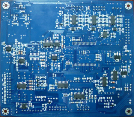
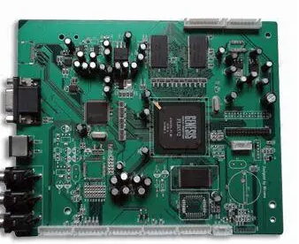
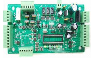
Surface mount technology, also known as surface mount technology (SMT), is an electronic assembly technology that directly pastes surface assembled components to the specified position of printed circuit board without drilling insertion holes on printed circuit board, and uses solder to form mechanical and electrical connection between components and printed circuit board.
Electronic products requiring surface mount are generally composed of printed circuit boards and surface mount components. Printed wire board (PWB) is a single-sided or double-sided multilayer material containing lines and pads. Surface mount components include surface mount components and surface mount devices. Surface mount components refer to various sheet passive components, such as resistance, capacitance, inductance, etc; Surface mount devices are packaged electronic devices, usually referring to various active devices, such as small outline package (SOP), ball grid array package (BGA), etc. Some components cannot be used in SMT, such as some connectors, transformers, large capacitors, etc.

3 surface mount technology process
Surface mount Dingyi includes two processes: and auxiliary. The process consists of printing, chip placement and reflow soldering. The production of any type of product must go through these three processes, and each part is essential; The auxiliary process is mainly composed of "dispensing" process and optical assisted automatic detection process. It is not necessary, but determined according to product characteristics and user needs.
Printed circuit boards can be divided into single-sided and double-sided products. Electronic products can also be divided into single-sided products (components need to be attached to one side of the printed circuit board) and double-sided products (components need to be attached to both sides of the printed circuit board). Figure 1 shows the surface mounting process flow of single-sided products. Figure 2 shows the surface mount process flow of double-sided products.
The purpose of printing process is to make the solder paste accurately printed to the printed circuit board through the joint action of template and printing equipment. The process elements involved in the printing process mainly include solder paste, template and printing system. Solder paste is an important material to connect components with printed circuit board and realize its electrical and mechanical connection. The solder paste is mainly composed of alloy and flux. In the welding process, they play their respective roles to complete the welding work. The template is used to accurately print the solder paste on the printed circuit board. The manufacturing method and opening design of the template have a great impact on the printing quality. Printing system mainly refers to printing equipment and printing parameters. The quality of printing equipment has a great impact on the printing accuracy. The reasonable matching between the repeated printing accuracy of printing equipment and the setting of printing parameters is an important guarantee for accurate printing. There are many printing parameters, but the key parameters affecting the printing effect are printing speed, scraper pressure, demoulding speed and demoulding distance. These key parameters need to be set and matched with each other. To improve printing quality. The printing speed is generally 12.7 ~ 203.2 mm / s, and the specific parameters depend on the scraper pressure and the physical properties of solder paste. The SMT process requires the printing scraper pressure to be 4.448 222 ~ 6.672 333 n.
The purpose of the patch process is to ensure that all parts are pasted to the printed circuit board accurately and quickly. The patch process mainly involves the patch machine and its patch capability. The placement ability of the placement machine is an important guarantee for accurate placement. The key technologies of the mounter include: motion, execution and high-speed feeding mechanism. Miniaturization technology; High speed machine vision recognition and lighting technology; High speed, high precision intelligent control technology; Parallel processing real-time multitasking technology; Equipment open flexible modularization technology and system integration technology.
Reflow soldering process is to realize the mechanical and electrical connection between the welding surface or pin of surface mount components and the PCB pad by melting the solder paste pre distributed on the PCB pad. Reflow welding can ensure excellent welding effect. The main process elements of reflow process are reflow furnace and its welding ability, which is mainly reflected in the heating system, cooling system, flux management system and inert gas protection system of reflow furnace. The heating system is related to heating efficiency, temperature control accuracy, temperature uniformity and stability; The functions of the cooling system are: when the peak temperature of reflow soldering is high, if it cannot be cooled quickly, the temperature of the substrate out of the reflow soldering furnace is too high, which is easy to cause substrate bending; Rapid cooling can refine the structure and prevent the thickening of intermetallic compounds. Improve reliability. The flux will volatilize during reflow soldering. If there is no ideal flux management system to timely remove the volatilized flux and filter it for circulation, the flux will enter the cooling area with the high-temperature air flow and condense in the heat sink and furnace, reduce the cooling effect and pollute the equipment and substrate. When the activity of the solder paste matched with the substrate is not good enough, or there are ultra-fine spacing elements and complex elements on the circuit board, and the substrate needs to pass through the reflow furnace for many times, consider filling the reflow furnace with inert gas to reduce the oxidation opportunity and improve the welding activity. The inert gas commonly used is nitrogen. The welding ability of the reflow furnace also needs to be brought into play by editing the control program of the reflow furnace. When the circuit board completing the patch passes through the reflow furnace, it generally goes through the preheating stage, insulation stage, reflow stage and cooling stage. Ensure the welding quality through the control procedure of reflow furnace.
The auxiliary process is used to assist the smooth installation and actively prevent detection and post detection. The auxiliary process is mainly composed of "point sticking" process and optical auxiliary automatic detection process. "Dispensing" process is to "point" the special glue to the lower part or periphery of the required components to properly protect the components, so as to ensure that the components will not fall off after repeated reflow welding; Reduce the stress impact on the components during mounting; Protect components from damage in complex service environments. The process elements of "dispensing" process mainly include "dispensing" equipment, special glue and setting of "dispensing" parameters. It is necessary to reasonably select equipment, glue and design parameter settings to ensure the process effect. The optical aided automatic detection process mainly includes: first, use special optical equipment to measure the thickness uniformity and printing accuracy of solder paste after printing, detect the accuracy of patch after patch, and detect the defective circuit board before reflow soldering and give an alarm in time; Second, after reflow soldering, use special optical equipment to detect the solder joint, detect the circuit board with solder joint defects and give an alarm. Special optical measuring equipment mainly includes visible light detection equipment and X-ray detection equipment. The former is mainly automatic optical inspection (AOI), and the latter is mainly three-dimensional and five-dimensional X-ray equipment. The former is mainly used to detect visual solder joints, while the latter can detect solder joints of non visual BGA parts in addition to visual solder joints. Whether to use auxiliary process is determined according to the characteristics of the products to be mounted.
4 principle and temperature curve of reflow soldering
The reflow soldering principle is analyzed from the reflow soldering temperature curve (Fig. 3): when the PCB enters the preheating area, the solvent and gas of the solder paste are evaporated, and the flux of the solder paste moistens the pads, component ends and pins. The solder paste softens, collapses and covers the pads, isolating the pads and component pins from oxygen; When the PCB enters the insulation area, the PCB and components are fully preheated. To prevent PCB from entering the reflow welding area suddenly and damaging PCB and components due to rapid temperature rise; When the PCB enters the reflow soldering area, the temperature rises rapidly to make the solder paste reach the melting state, and the liquid solder wetts, diffuses, diffuses or reflows the PCB pads, component ends and pins to form solder contacts; The PCB enters the cooling area, the solder joint solidifies, and the whole reflow soldering is completed.
During reflow soldering, the solder paste needs to be volatilized by solvent. The flux removes the oxide on the surface of the weldment, the solder paste melts and flows again, and the solder paste cools and solidifies. Therefore, in the reflow process, the welding temperature is mainly divided into four temperature zones: preheating zone, insulation zone, reflow zone and cooling zone. The preheating zone is room temperature to 120 degree Celsius; The insulation area is 120 degree Celsius ~ 170 degree Celsius; The reflux zone is 170 degree Celsius ~ 230 degree Celsius, and the temperature is 210 degree Celsius ~ 230 degree Celsius; The cooling zone is reduced from 210 degree Celsius to about 100 degree Celsius.
Temperature curve is the key to ensure welding quality. The heating slope and peak temperature of actual temperature curve and solder paste temperature curve shall be basically consistent. The heating rate before 160 degree Celsius shall be controlled at 1 degree Celsius / S ~ 2 degree Celsius / s. if the heating rate is too fast, on the one hand, the components and PCB will be heated too fast, which is easy to damage the components and cause PCB deformation; On the other hand, the solvent in solder paste volatilizes too fast. It is easy to spill metal components and produce solder balls. The peak temperature is generally set to be 20 degree Celsius ~ 40 degree Celsius higher than the melting temperature of solder paste (for example, the melting point of Sn63 / Pb37 solder paste is 183 degree Celsius, and the peak temperature should be set at 205 degree Celsius ~ 230 degree Celsius), and the return (RE) flow time is 10 ~ 60 s. low peak temperature or short return (RE) flow time will lead to insufficient welding and non melting of solder paste in serious cases; Too high peak temperature or long return (RE) time will cause metal powder oxidation, affect welding quality, and even damage components and PCBs.
Basis for setting the reflow soldering temperature curve: the temperature curve of the solder paste used, according to the material, thickness, multilayer board and size of PCB; Density and size of components carried on the surface assembly board, and whether there are BGA, CSP and other special components; Specific conditions of the equipment, such as the length of the heating zone, the material of the heating source, the structure of the reflow furnace and the heat conduction mode.
In the actual production of a certain type of printed board, the temperature areas set due to the equipment are: heating area, insulation area, rapid heating area and reflux area. The solder paste is sn63pb37 solder paste with a melting point of 183 degree Celsius. A certain reflow welding furnace is used for welding. Each printed board component must be designed with appropriate welding parameters to achieve a temperature curve for each printed board. Figure 4 shows the standard reflow soldering temperature curve, and figure 5 shows the actual reflow soldering temperature curve of a printed board.
This is a reflow soldering furnace in 9 temperature zone. There are 3 test points for the actual temperature test, of which Fig. 5 is the actual temperature curve. The parameter setting of temperature zone shall meet the following requirements: 1) temperature rise zone: the temperature rise rate from room temperature to 100 degree Celsius shall not exceed 2 degree Celsius / S; 2) Insulation area: from 100 degree Celsius ~ 150 degree Celsius for 70 ~ 120 s; 3) Rapid heating zone: the holding time from 150 degree Celsius ~ 183 degree Celsius shall not exceed 30s, and the heating rate shall be 2 ~ 3 degree Celsius / s: 4) reflux zone: the temperature is 205 degree Celsius ~ 230 degree Celsius, and the time above the liquidus is 40 ~ 60 s; 5) Cooling zone: the cooling rate is 2 ~ 4 degree Celsius / s. By comparing the theoretical and actual PCB temperature curves in Figure 4 and figure 5, the actual reflow temperature area is within the standard temperature range, so it is concluded that the welding of the surface mounted devices on the PCB meets the requirements and ensures the electrical performance of the surface mounted devices on the PCB. Special attention: the reflow furnace must be tested every week. Compare the test temperature curve with the standard temperature curve to determine whether they are completely consistent. The main check parameters include: heating rate in the heating zone, holding time in the holding zone, heating rate in the rapid heating zone and reflux zone, peak temperature, time above the liquidus, cooling rate in the cooling zone, and whether there is abnormal fluctuation in the curve.
5 Conclusion
Surface mount technology penetrates into various fields, which can directly affect the welding level of electronic products, as well as the performance and quality of electronic products. This paper describes the whole process of surface mount technology, and expounds the principle and temperature curve of reflow welding in the welding process. Comparing the standard reflow soldering temperature curve and the actual reflow soldering temperature curve of a printed board in the actual production process, as long as the actual reflow soldering temperature area is within the standard temperature range, the performance index of mounted components can be met.